1-28 Cisco 7010 Hardware Installation and Maintenance
Physical Description
section “FDDI Connection Equipment” in the chapter “Preparing for Installation.” For descriptions
of FDDI network connections, refer to the section “FDDI Connections” in the chapter “Installing the
Router.”
Fast Serial Interface Processor (FSIP)
The FSIP provides four or eight channel-independent, synchronous serial ports that support full
duplex operation at T1 (1.544 Mbps) and E1 (2.048 Mbps) speeds. Each port supports any of the
available interface types: EIA/TIA-232, EIA/TIA-449, V.35, X.21, EIA-530, and E1-G.703/G.704.
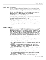
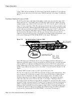
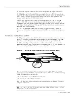
Figure 1-18 shows an eight-port FSIP. The eight ports are divided into two four-port modules, each
of which is controlled by a dedicated Motorola MC68040 processor and contains 128 kilobytes (KB)
of static random-access memory (SRAM). Each module can support up to four T1 or three E1
interfaces, and an aggregate bandwidth of up to 6.132 Mbps at full-duplex operation. The type of
electrical interface, the amount of traffic, and the types of external data service units (DSUs)
connected to the ports affect actual rates. For information on setting up high-speed interfaces, refer
to the section “Replacing RSP7000 DRAM SIMMs” in the chapter “Maintenance.”
Figure 1-18
Fast Serial Interface Processor (FSIP)
Each FSIP comprises an FSIP board with two or four port adapters installed. Additional port
adapters are available as spares so that you can replace one that fails; however, you cannot upgrade
a four-port FSIP to an eight-port by adding port adapters. The 4-port FSIP is not constructed to
support additional ports after it leaves the factory; it contains the circuitry to control only one 4-port
module. For port adapter descriptions, refer to the section “Universal Serial Port Adapters” in this
chapter.
The default FSIP microcode resides on a PLCC-type ROM in socket U81.
The Cisco 7010 supports up to three FSIPs for a maximum of 24 high-speed serial interfaces. There
are no restrictions on slot locations or sequence; you can install FSIPs in any available interface
processor slots. For descriptions of serial connection equipment, refer to the section “Serial
Connection Equipment” in the chapter “Preparing for Installation.” For examples of network
connections, refer to the section “Serial Connections” in the chapter “Installing the Router.”
All interface types except EIA-530 are individually configurable for operation with either external
timing (DTE mode) or internal timing (DCE mode); EIA-530 operates with external timing only. In
addition, all interfaces support nonreturn to zero (NRZ) and nonreturn to zero inverted (NRZI)
format, and both 16-bit and 32-bit cyclic redundancy checks (CRCs). The default configuration is
for NRZ format and 16-bit CRC. You can change these default settings with software commands.
(See the section “Replacing RSP7000 DRAM SIMMs” in the chapter “Maintenance.”)
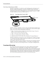
H2004
Module 1, ports 0-3
Module 2, ports 4-7
Port adapters
Translation of DCE LED
states for DCE ports:
RxC
RxD
TxC
CONN
TxC
TxD
RxC
CONN
=
=
=
=
U81, PLCC socke
with microcode R
Enabled
RxC
RxD
TxC
CONN
Содержание TelePresence Server 7010
Страница 10: ...x Cisco 7010 Hardware Installation and Maintenence ...
Страница 14: ...iv Cisco 7010 Hardware Installation and Maintenance Document Conventions ...
Страница 112: ...2 52 Cisco 7010 Hardware Installation and Maintenance Initial Configuration Information Page ________ ...
Страница 148: ...3 36 Cisco 7010 Hardware Installation and Maintenance Using the Flash Memory Card ...
Страница 158: ...4 10 Cisco 7010 Hardware Installation and Maintenance Troubleshooting the Processor Subsystem ...
Страница 242: ...5 84 Cisco 7010 Hardware Installation and Maintenance Replacing Internal Components ...
Страница 258: ...A 16 Cisco 7010 Hardware Installation and Maintenance MIP Interface Cable Pinouts ...
Страница 270: ...B 12 Cisco 7010 Hardware Installation and Maintenance Interface Processor LEDs ...
Страница 274: ...C 4 Cisco 7000 Hardware Installation and Maintenance ...
Страница 287: ...Index 13 ...


