1-10 Cisco 7010 Hardware Installation and Maintenance
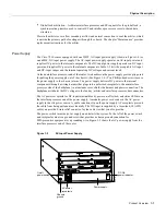
Physical Description
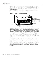
Figure 1-7
Router System Architecture
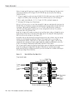
The backplane slots are keyed so that the processor modules can be installed only in the slots
designated for them. Keys on the backplane fit into two key guides on each module. (See Figure 1-8.)
Although the RP, SP, and SSP each use unique keys, all three interface processor slots use the same
key, so you can install an interface processor in any interface processor slot.
Caution
When installing an RP, SP, SSP, or interface processor, ensure that you are installing it in
the appropriate slot to avoid damaging the key guides or the backplane.
Figure 1-8
Backplane Slot Keys
RP
SP or SSP
CxBus FIP
Single-port FDDI
interface processor
• 68040 CPU
• Flash EPROM
• 16-MB DRAM
• ENVM Logic
CxBus FSIP
4/8 port fast serial
interface processor
CxBus TRIP
2/4-port Token Ring
interface processor
Distributed processing
H3141
RP
SP
(or SSP)
EIP
key guide
key guide
Key guides on Interface processors, SP (or SSP), and RP
H3142
Rear of
processor module
Left
Right
Right
Left
Содержание TelePresence Server 7010
Страница 10: ...x Cisco 7010 Hardware Installation and Maintenence ...
Страница 14: ...iv Cisco 7010 Hardware Installation and Maintenance Document Conventions ...
Страница 112: ...2 52 Cisco 7010 Hardware Installation and Maintenance Initial Configuration Information Page ________ ...
Страница 148: ...3 36 Cisco 7010 Hardware Installation and Maintenance Using the Flash Memory Card ...
Страница 158: ...4 10 Cisco 7010 Hardware Installation and Maintenance Troubleshooting the Processor Subsystem ...
Страница 242: ...5 84 Cisco 7010 Hardware Installation and Maintenance Replacing Internal Components ...
Страница 258: ...A 16 Cisco 7010 Hardware Installation and Maintenance MIP Interface Cable Pinouts ...
Страница 270: ...B 12 Cisco 7010 Hardware Installation and Maintenance Interface Processor LEDs ...
Страница 274: ...C 4 Cisco 7000 Hardware Installation and Maintenance ...
Страница 287: ...Index 13 ...


