


5-14 Cisco 7010 Hardware Installation and Maintenance
Installing and Configuring Processor Modules
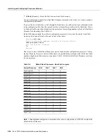
Hardware Configuration Register Settings
The hardware configuration register (see Figure 5-4) comprises the upper 32 pins of a 50-pin jumper
block located above the Flash memory card port on the RP. You can define system boot instructions,
set broadcast addresses and console baud rates, or instruct the router to perform factory diagnostics
at startup by installing jumpers on specific pins. Jumper bit (or position) 0 is the top pair of pins. To
set a bit to 1, insert a jumper. To clear a bit to 0, remove the jumper.
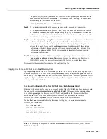
To change configuration register settings, you must turn off the system power and remove the RP.
Figure 5-5 shows the configuration register with the factory default setting, with jumpers installed
on bits 0 and 8. Bit 0 instructs the system to boot from ROM; bit 8 instructs the system to ignore the
Break key on the console terminal keyboard.
Figure 5-5
Configuration Register Factory Default Settings
The lowest four bits of the configuration register (bits 3 through 0) form the boot field. The boot field
specifies a number in binary. When the boot field is set to either 0 or 1 (0-0-0-0 or 0-0-0-1) the
system ignores any boot instructions in the configuration file. When the boot field is set to 0, you
must boot the operating system manually by giving a b (or boot) command to the system bootstrap
program or rom monitor. You can enter the boot command only, or include additional boot
instructions with the command such as the name of a file stored in Flash memory or a file that you
specify for netbooting. If you use the boot command only, without specifying a file or any other boot
instructions, the system boots from the ROM image. Otherwise, you can instruct the system to boot
from a specific image such as a Flash file (boot system flash filename), or to netboot by sending
broadcast TFTP requests (boot system filename) or a direct TFTP request to a specific server (boot
system filename address). When the boot field is set to 1 (the factory default), the system boots from
ROM. Boot field settings of 0 and 1 both override any boot instructions in the system configuration
file.
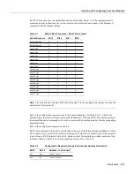
If you set the boot field to any bit pattern other than 0 or 1, the system uses the resulting number to
form a file name for netbooting. To form the file name, the system starts with cisco and links the
octal equivalent of the boot field value (jumper setting) and the processor type in the format
cisco<jumpervalue>-<processorname>. (Table 5-1 lists the default boot file names or actions for
2
3
4
5
6
7
8
9
10
11
12
13
14
15
1
Bit 15 Run factory diagnostics at startup
Bit 14 Net/subnet broadcast address 000.000.000.000
Bit 13 Load software from ROM after five boot-load failures
Bits11–12 Console baud rate 9600
Bit 10 Host broadcast address 000.000.000.000
Bit 8 Ignore console Break key
Bits 4–7 Not used (leave cleared)
Bit 0 Boot from ROM
H1373a
0
Содержание TelePresence Server 7010
Страница 10: ...x Cisco 7010 Hardware Installation and Maintenence ...
Страница 14: ...iv Cisco 7010 Hardware Installation and Maintenance Document Conventions ...
Страница 112: ...2 52 Cisco 7010 Hardware Installation and Maintenance Initial Configuration Information Page ________ ...
Страница 148: ...3 36 Cisco 7010 Hardware Installation and Maintenance Using the Flash Memory Card ...
Страница 158: ...4 10 Cisco 7010 Hardware Installation and Maintenance Troubleshooting the Processor Subsystem ...
Страница 242: ...5 84 Cisco 7010 Hardware Installation and Maintenance Replacing Internal Components ...
Страница 258: ...A 16 Cisco 7010 Hardware Installation and Maintenance MIP Interface Cable Pinouts ...
Страница 270: ...B 12 Cisco 7010 Hardware Installation and Maintenance Interface Processor LEDs ...
Страница 274: ...C 4 Cisco 7000 Hardware Installation and Maintenance ...
Страница 287: ...Index 13 ...