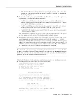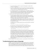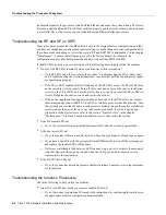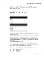
Maintenance 5-9
Installing and Configuring Processor Modules
Microcode Component Replacement
The SP (or SSP) and each interface processor contain default microcode, which is an image of
board-specific software instructions on a single ROM device on each board. Microcode operates
with the system software and controls features and functions that are unique to an interface processor
type. New features and enhancements to the system or interfaces are often implemented in
microcode upgrades. Although each processor type contains the latest available microcode version
(in ROM) when it leaves the factory, updated microcode images are periodically distributed with
system software images to enable new features, improve performance, or fix bugs in earlier versions.
The latest available microcode version for each interface processor type is bundled with each new
system software maintenance upgrade; the bundled images are distributed as a single image on
floppy disk or a Flash memory card.
Note
We strongly recommend that the microcode bundled with the system software be used as a
package. Overriding the bundle could possibly result in incompatibility between the various
interface processors in the system.
Although most upgrades support the downloadable microcode feature and are distributed on floppy
disk, some images may require ROM replacement. If necessary, use the following instructions to
replace an interface processor EPROM in case Flash memory is damaged or otherwise not available,
or to change the default microcode on a board for any other reason. The replacement procedures are
the same for each board with the exception of the FSIP, which uses a PLCC-type package for the
microcode.
You must use a PLCC extractor to remove the FSIP microcode component. (See Figure 5-3.) You
cannot use a small flat-blade screwdriver to pry it out of the socket as with the older type of
integrated circuits (ICs). A PLCC IC does not have legs or pins that plug into the socket; instead, the
contacts are on the sides of the IC and along the inner sides of the socket. When the IC is seated in
the socket, the top of the IC is flush with the top of the socket. Forcing a small screwdriver or other
tool between the IC and the sides of the socket to pry out the IC will damage the component or the
socket or both, and you will have to replace them.
Содержание TelePresence Server 7010
Страница 10: ...x Cisco 7010 Hardware Installation and Maintenence ...
Страница 14: ...iv Cisco 7010 Hardware Installation and Maintenance Document Conventions ...
Страница 112: ...2 52 Cisco 7010 Hardware Installation and Maintenance Initial Configuration Information Page ________ ...
Страница 148: ...3 36 Cisco 7010 Hardware Installation and Maintenance Using the Flash Memory Card ...
Страница 158: ...4 10 Cisco 7010 Hardware Installation and Maintenance Troubleshooting the Processor Subsystem ...
Страница 242: ...5 84 Cisco 7010 Hardware Installation and Maintenance Replacing Internal Components ...
Страница 258: ...A 16 Cisco 7010 Hardware Installation and Maintenance MIP Interface Cable Pinouts ...
Страница 270: ...B 12 Cisco 7010 Hardware Installation and Maintenance Interface Processor LEDs ...
Страница 274: ...C 4 Cisco 7000 Hardware Installation and Maintenance ...
Страница 287: ...Index 13 ...

