


5-10 Cisco 7010 Hardware Installation and Maintenance
Installing and Configuring Processor Modules
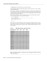
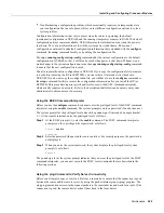
Figure 5-3
Removing a Microcode Component from a PLCC-Type Package
Tools Required
You need the following tools to replace the microcode component:
•
Chip extractor or puller (you need a PLCC-type extractor to remove the FSIP component)
•
Antistatic mat or foam pad
•
ESD-preventive grounding strap (a disposable wriststrap is included in microcode upgrade kits)
Replacing the ROM
Following are the steps for replacing the microcode ROM device on the SP (or SSP) and any
interface processor. Refer to the illustrations of the individual interface processors in the section
“Interface Processors” in the chapter “Product Overview” for socket locations.
Caution
Handle interface processors by the handles and carrier edges only, and always use a
grounding strap to prevent ESD damage.
Step 1
If you are replacing the component on an interface processor, check the state of each
interface before removing the interface processor and note any that are shutdown.
Step 2
If you are removing and reinserting the SP (or SSP), shutdown the system.
Step 3
Follow the steps in a previous section “Removing CxBus Interface Processors” to remove
the interface processor or SP (or SSP) from the chassis. You can leave the cables connected
if you perform the replacement close to the chassis to avoid straining the interface cables
attached to an adjacent interface processor. Otherwise, label the cables before
disconnecting them to avoid crossing them later.
Step 4
Place the removed interface processor on an antistatic mat or foam.
PLCC extractor tool
PLCC PROM
PLCC extractor slot
PLCC socket
Squeeze here
H1579a
PLCC extractor slot
Squeeze here
Содержание TelePresence Server 7010
Страница 10: ...x Cisco 7010 Hardware Installation and Maintenence ...
Страница 14: ...iv Cisco 7010 Hardware Installation and Maintenance Document Conventions ...
Страница 112: ...2 52 Cisco 7010 Hardware Installation and Maintenance Initial Configuration Information Page ________ ...
Страница 148: ...3 36 Cisco 7010 Hardware Installation and Maintenance Using the Flash Memory Card ...
Страница 158: ...4 10 Cisco 7010 Hardware Installation and Maintenance Troubleshooting the Processor Subsystem ...
Страница 242: ...5 84 Cisco 7010 Hardware Installation and Maintenance Replacing Internal Components ...
Страница 258: ...A 16 Cisco 7010 Hardware Installation and Maintenance MIP Interface Cable Pinouts ...
Страница 270: ...B 12 Cisco 7010 Hardware Installation and Maintenance Interface Processor LEDs ...
Страница 274: ...C 4 Cisco 7000 Hardware Installation and Maintenance ...
Страница 287: ...Index 13 ...