Maintenance 5-7
Installing and Configuring Processor Modules
Installing CxBus Interface Processors
You can install interface processors in any of the three interface processor slots, numbered 0 through
2 from the bottom slot upward when viewing the chassis from the interface processor end.
(See Figure 1-3.) The top slot contains the RP, and the slot directly below the RP contains the SP (or
SSP). Blank interface processor fillers are installed in slots without interface processors to maintain
consistent air flow through the interface processor compartment.
Following are installation steps for the CxBus interface processors, which support OIR and can be
removed and installed while the system is operating. The RP, SP (or SSP), RSP7000, or RSP7000CI
are required system components. You must turn off the system power before removing or installing
them. After you have turned the system power off, the installation steps for the RP, SP (or SSP),
RSP7000, and RSP7000CI are the same as those for the interface processors.
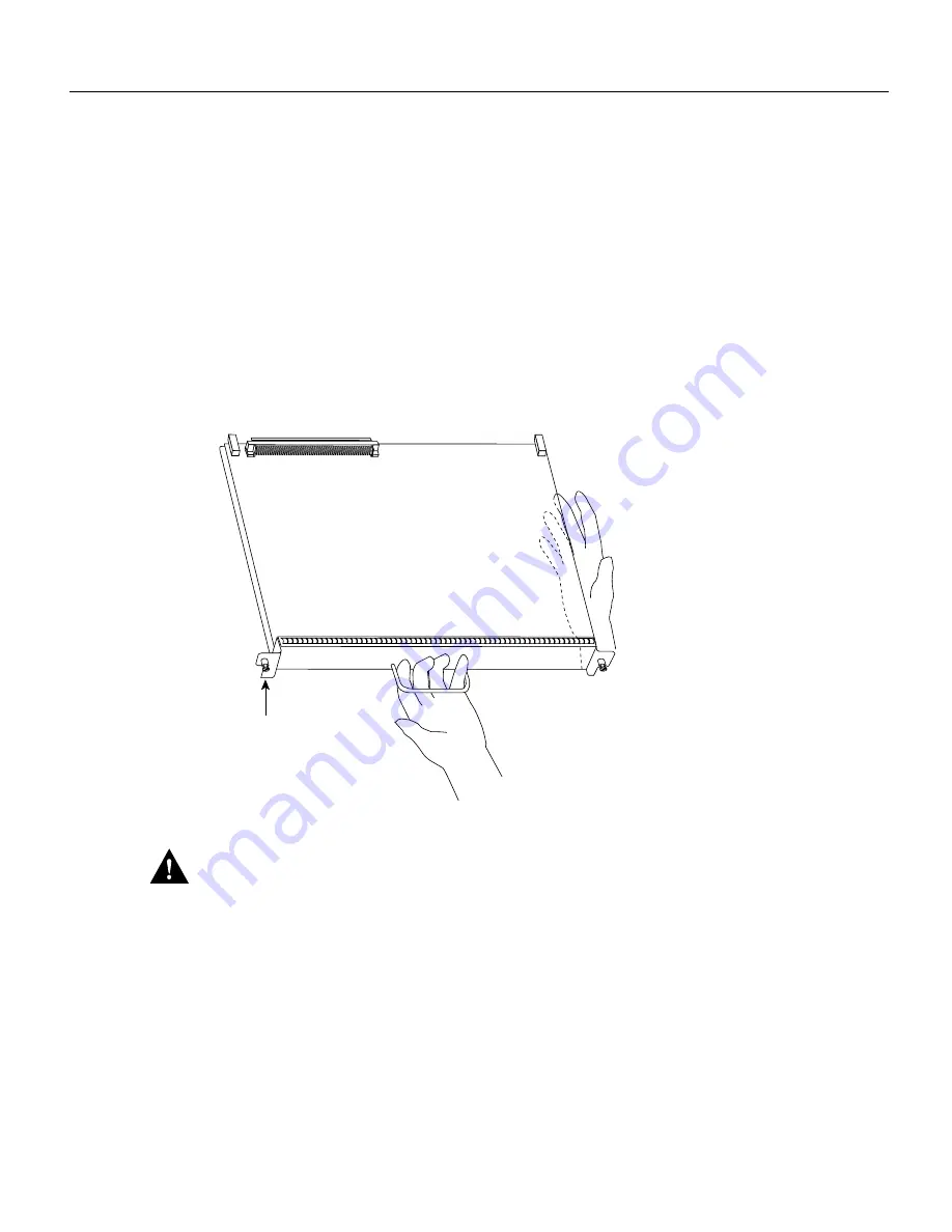
Figure 5-2
Handling an Interface Processor during Installation
Caution
Handle interface processors by the handles and carrier edges only to prevent ESD damage.
Step 1
Choose a slot for the new interface processor and ensure that there is enough clearance to
accommodate any interface equipment that you will connect directly to the interface
processor ports. (For example, 10BASE-T Ethernet transceivers that connect directly to
EIP ports may be wider than the interface processor and can obstruct connections on
adjacent interface processors.)
Step 2
Interface processors are secured with two captive installation screws. Use a number 1
Phillips or a 1/4-inch flat-blade screwdriver to loosen the two captive installation screws
and remove the interface processor filler (or the existing interface processor) from the slot
to be filled.
Step 3
Hold the interface processor handle with one hand, and place your other hand under the
carrier to support it. (See Figure 5-2.) Avoid touching the board.
H1985
Captive installation
screws
Содержание TelePresence Server 7010
Страница 10: ...x Cisco 7010 Hardware Installation and Maintenence ...
Страница 14: ...iv Cisco 7010 Hardware Installation and Maintenance Document Conventions ...
Страница 112: ...2 52 Cisco 7010 Hardware Installation and Maintenance Initial Configuration Information Page ________ ...
Страница 148: ...3 36 Cisco 7010 Hardware Installation and Maintenance Using the Flash Memory Card ...
Страница 158: ...4 10 Cisco 7010 Hardware Installation and Maintenance Troubleshooting the Processor Subsystem ...
Страница 242: ...5 84 Cisco 7010 Hardware Installation and Maintenance Replacing Internal Components ...
Страница 258: ...A 16 Cisco 7010 Hardware Installation and Maintenance MIP Interface Cable Pinouts ...
Страница 270: ...B 12 Cisco 7010 Hardware Installation and Maintenance Interface Processor LEDs ...
Страница 274: ...C 4 Cisco 7000 Hardware Installation and Maintenance ...
Страница 287: ...Index 13 ...

