Preparing for Installation 2-41
Preparing Network Connections
All serial signals are subject to distance limits, beyond which a signal degrades significantly or is
completely lost. For specific cabling distance limitations, refer to the section “Distance Limitations”
in this chapter. The distance and rate limits in these descriptions are the IEEE-recommended
maximum speeds and distances for signaling; however, you can usually get good results at speeds
and distances far greater than these. For instance, the recommended maximum rate for V.35 is
2 Mbps, but 4 Mbps is commonly used without any problems. If you understand the electrical
problems that might arise and can compensate for them, you should get good results with rates and
distances greater than those shown here; however, do so at your own risk. We do not recommend
exceeding the published speed and distance specifications.
EIA/TIA-232 Connections
By far the most common interface standard in the U.S., EIA/TIA-232 supports unbalanced circuits
at signal speeds up to 64 kbps. The router (FSIP) end of all EIA/TIA-232 adapter cables is a
high-density 60-pin plug. The opposite (network) end of the adapter cable is a standard 25-pin
D-shell connector (known as a DB-25) that is commonly used for EIA/TIA-232 connections.
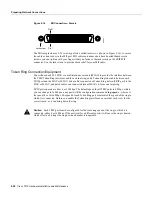
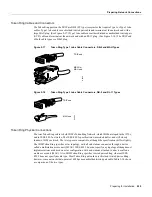
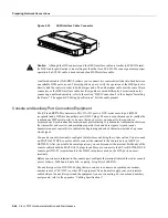
Figure 2-34 shows the connectors at the network end of the adapter cable. The system Console and
Auxiliary ports on the RP also use EIA/TIA-232 connections; however the FSIP ports support
synchronous connections, and the Console and Auxiliary ports support only asynchronous
connections. For further information on the RP ports, refer to the section “Console and Auxiliary
Port Connection Equipment” in this chapter.
Figure 2-34
EIA/TIA-232 Adapter Cable Connectors, Network End
EIA/TIA-449 Connections
EIA/TIA-449, which supports balanced (EIA/TIA-422) and unbalanced (EIA/TIA-423)
transmissions, is a faster (up to 2 Mbps) version of EIA/TIA-232 that provides more functions and
supports transmissions over greater distances. The EIA/TIA-449 standard was intended to replace
EIA/TIA-232, but it was not widely adopted. Industry’s resistance to convert to EIA/TIA-449 was
due primarily to the large installed base of DB-25 hardware and to the larger size of the 37-pin
EIA/TIA-449 connectors, which limited the number of connections possible (fewer than possible
with the smaller, 25-pin EIA/TIA-232 connector).
The router (FSIP) end of all EIA/TIA-449 adapter cables is a high-density 60-pin plug. The opposite
(network) end of the adapter cable provides a standard 37-pin D-shell connector commonly used for
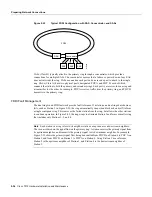
EIA/TIA-449 connections. Figure 2-35 shows the connectors at the network end of the adapter
cable. EIA/TIA-449 cables are available as either DTE (DB-37 plug) or DCE (DB-37 receptacle).
H1343a
DTE
DCE
Содержание TelePresence Server 7010
Страница 10: ...x Cisco 7010 Hardware Installation and Maintenence ...
Страница 14: ...iv Cisco 7010 Hardware Installation and Maintenance Document Conventions ...
Страница 112: ...2 52 Cisco 7010 Hardware Installation and Maintenance Initial Configuration Information Page ________ ...
Страница 148: ...3 36 Cisco 7010 Hardware Installation and Maintenance Using the Flash Memory Card ...
Страница 158: ...4 10 Cisco 7010 Hardware Installation and Maintenance Troubleshooting the Processor Subsystem ...
Страница 242: ...5 84 Cisco 7010 Hardware Installation and Maintenance Replacing Internal Components ...
Страница 258: ...A 16 Cisco 7010 Hardware Installation and Maintenance MIP Interface Cable Pinouts ...
Страница 270: ...B 12 Cisco 7010 Hardware Installation and Maintenance Interface Processor LEDs ...
Страница 274: ...C 4 Cisco 7000 Hardware Installation and Maintenance ...
Страница 287: ...Index 13 ...


