Cisco TelePresence IX5000 Скачать руководство пользователя страница 2


2

IX5000 Field-Replaceable Units and Country- and Region-Specific Power Connectors


    Finding the System Serial Number

Finding the System Serial Number

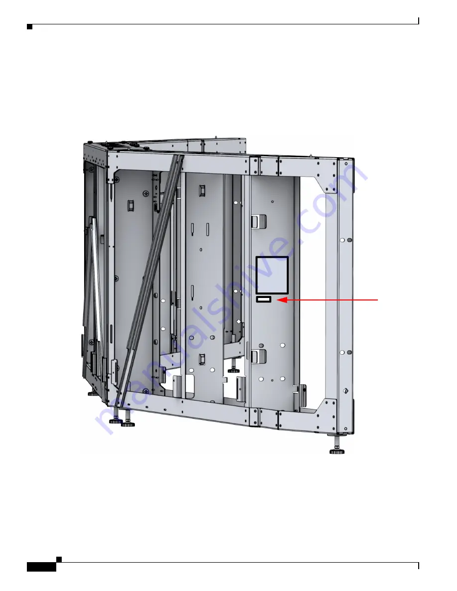
You might need the serial number of your IX5000 to order FRUs. The serial number is located on the 
pillar of the lower left display frame, underneath the compliance label. It is in the arrowed area shown 
in white in 

Figure 1

Figure 1

Serial Number Label Location

Содержание TelePresence IX5000

Страница 1: ...d replaceable units FRUs for the Cisco TelePresence System IX5000 and includes the following sections Finding the System Serial Number page 2 List of Field Replaceable Units page 3 Replacing the Camera Part Number CTS 5K CAM CLSTR page 14 Replacing a Display Part Number CTS 5K 70 G1 page 18 Replacing a Codec Part Number CTS 5K ENCODER or CTS 5K HOSTCPU page 36 Replacing a Microphone Mic Bar Part N...

Страница 2: ...rial Number Finding the System Serial Number You might need the serial number of your IX5000 to order FRUs The serial number is located on the pillar of the lower left display frame underneath the compliance label It is in the arrowed area shown in white in Figure 1 Figure 1 Serial Number Label Location ...

Страница 3: ...l and Serial Number Location List of Field Replaceable Units Table 1 provides you with a list of the FRUs for the Cisco TelePresence System IX5000 Table 1 List of Field Replaceable Units FRU Name Description Diagram Reference CAB DV10 4M 4 meter flat grey Ethernet cable for Touch 10 CTS 5K 70 G1 70 inch Display CTS 5K AMP PWR Subwoofer amplifier power supply CTS 5K AMP SUBWFR Subwoofer amplifier ...

Страница 4: ...L R2 LAP CTS IX5000 Cable kit back row table Ethernet Lapconns1 CX2 C7 C18 CTS 5K CBL R2 MIC CTS IX5000 Cable kit back row table audio1 AX2 AX3 A7 A18 CTS 5K CBL R2 SW CTS IX5000 Cable kit back row switches1 EX2 EX3 CTS 5K CBL RTR Presentation cable with three headed connector includes cable and cable retractor L7 L8 CTS 5K CBL RUN Cable runner assembly includes cable runner and cable runner cover...

Страница 5: ...T CTS IX5000 front row table cable management assembly CTS 5K MUTE BTN Mute button IX5000 Seismic bracket kit CTS 5K SHTML MISC Miscellaneous sheetmetal kit CTS 5K SPKR Speaker CTS 5K SUBWOOFER Subwoofer CTS 5K TBL H 18S Front and second row tabletop set hickory CTS 5K TBL H 6S Front row tabletop set hickory CTS 5K TBL M 18S Front and second row tabletop set maple CTS 5K TBL M 6S Front row tableto...

Страница 6: ...Carton document at http www cisco com c en us td docs telepresence ix5000 carton_contents ix5000_carton_and_parts_list html and search for the cable kit FRU name removing the equal sign For example for a complete list of the cables in the Encoder Decoder cable kit open the Parts List Sorted by Carton document and search for CTS 5K CBL CODEC Table 2 Region and Country Specific Power Cables and Tabl...

Страница 7: ...ectors PWR CORD10 BZ TelePresence 10 Power Cord Brazil PWR CORD10 CE TelePresence 10 Power Cord Central Europe PWR CORD10 CN TelePresence 10 Power Cord China PWR CORD10 ID TelePresence 10 Power Cord India UAE South Africa Table 2 Region and Country Specific Power Cables and Table Leg Laptop Power Connectivity Power Cord ID Description ...

Страница 8: ... Leg Connectors PWR CORD10 ISR TelePresence 10 Power Cord Israel PWR CORD10 ITA TelePresence 10 Power Cord Italy PWR CORD10 JP TelePresence 10 Power Cord Japan PWR CORD NA TelePresence 10 Power Cord North America Table 2 Region and Country Specific Power Cables and Table Leg Laptop Power Connectivity Power Cord ID Description ...

Страница 9: ...wer and Table Leg Connectors PWR CORD10 SWI TelePresence 10 Power Cord Switzerland PWR CORD10 UK TelePresence 10 Power Cord United Kingdom CTS LAPCONN AP TelePresence Laptop Connectivity Asia Pacific Table 2 Region and Country Specific Power Cables and Table Leg Laptop Power Connectivity Power Cord ID Description ...

Страница 10: ...wer and Table Leg Connectors CTS LAPCONN AR TelePresence Laptop Connectivity Argentina CTS LAPCONN AU TelePresence Laptop Connectivity Australia CTS LAPCONN BZ TelePresence Laptop Connectivity Brazil Table 2 Region and Country Specific Power Cables and Table Leg Laptop Power Connectivity Power Cord ID Description ...

Страница 11: ...r and Table Leg Connectors CTS LAPCONN CE TelePresence Laptop Connectivity Central Europe CTS LAPCONN CN TelePresence Laptop Connectivity China CTS LAPCONN ID TelePresence Laptop Connectivity India UAE Table 2 Region and Country Specific Power Cables and Table Leg Laptop Power Connectivity Power Cord ID Description ...

Страница 12: ... Power and Table Leg Connectors CTS LAPCONN ISR TelePresence Laptop Connectivity Israel CTS LAPCONN ITA TelePresence Laptop Connectivity Italy CTS LAPCONN JP TelePresence Laptop Connectivity Japan Table 2 Region and Country Specific Power Cables and Table Leg Laptop Power Connectivity Power Cord ID Description ...

Страница 13: ...NN NA TelePresence Laptop Connectivity North America CTS LAPCONN SA TelePresence Laptop Connectivity South Africa CTS LAPCONN SWI TelePresence Laptop Connectivity Switzerland CTS LAPCONN UK TelePresence Laptop Connectivity United Kingdom Table 2 Region and Country Specific Power Cables and Table Leg Laptop Power Connectivity Power Cord ID Description ...

Страница 14: ...ocedure easier only one person is required a While wearing gloves grasp the fascia from the left side at the top corner and pull it outward Let the fascia swing outward from its hinge b Set the left side of the fascia on the ground leaving it upright Do not twist or put undue stress on the joints c Move to the center of the system pull the center of the fascia outward and set that part on the grou...

Страница 15: ... the endpoint structure The cover attaches to the structure with magnets Step 4 While still wearing gloves remove the upper fascia by grasping the left side of the fascia and pulling it out Continue holding the left side while moving towards the center of the system Gently fold and join the left side onto the center making sure not to bend or crease the fascia it should hold a U shape where it fol...

Страница 16: ...r CTS 5K CAM CLSTR Fold it over once more and join the center section with the right section Continue removing the fascia until the entire fascia is removed from the system Set the fascia on the ground and leave it in three U shaped sections Step 5 Remove the center speaker cover using 2 and 3 Phillips screwdrivers ...

Страница 17: ...ion Be careful not to jar the center light panel loose when you remove the speaker cover Step 6 Find the pigtail wire coming from the left side of the center light panel and disconnect the connector at the end of the pigtail Then lift the center light panel upward and pull the lower part outward and remove it from the endpoint structure ...

Страница 18: ...l and center speaker cover Step 10 Replace the upper facade and lens hood cover camera cover Step 11 Power on the PDUs on the lower part of the endpoint structure Step 12 Log into the Cisco TelePresence Administrative UI and perform the camera alignment procedure Step 13 Replace the lower facade For detailed steps and additional illustrations refer to the IX5000 installation guide and the first ti...

Страница 19: ...at the top corner and pull it outward Let the fascia swing outward from its hinge b Set the left side of the fascia on the ground leaving it upright Do not twist or put undue stress on the joints c Move to the center of the system pull the center of the fascia outward and set that part on the ground d Take the right end of the fascia at the upper corner pull it outward and set that on the ground L...

Страница 20: ...f the fascia and pulling it out Continue holding the left side while moving towards the center of the system Gently fold and join the left side onto the center making sure not to bend or crease the fascia it should hold a U shape where it folds over not a V shape Move to the right of the system and continue to pull the fascia outward Fold it over once more and join the center section with the righ...

Страница 21: ...21 IX5000 Field Replaceable Units and Country and Region Specific Power Connectors Replacing a Display Part Number CTS 5K 70 G1 Step 5 Remove the horizontal display trim from the underside of the panels ...

Страница 22: ...p 6 While wearing gloves remove the right or left PET panels depending on which display requires replacement by pulling them upward and outward Step 7 Remove the lower corner cabinet Remove the right cabinet for the right display remove the left cabinet for the left display Four screws attach the cabinet to the lower display frame ...

Страница 23: ...art Number CTS 5K 70 G1 Step 8 Remove the upper and cabinet right for the right display left for the left display Step 9 Remove the vertical bezel extrusions Remove the two screws on the lower part of the extrusion then rotate the extrusion upward from the bottom and lift it free of the endpoint structure ...

Страница 24: ...ors Replacing a Display Part Number CTS 5K 70 G1 Step 10 Remove the right or left speaker cover Remove the four captive screws and two recessed screws Step 11 Disconnect the pigtail connector on the side of the light panel and remove the light panel above the display to be removed ...

Страница 25: ...er Connectors Replacing a Display Part Number CTS 5K 70 G1 Step 12 Remove the speakers that are above the display you want to replace right speakers for right display center speakers for center display and left speakers for left display There are four screws per speaker ...

Страница 26: ...6 IX5000 Field Replaceable Units and Country and Region Specific Power Connectors Replacing a Display Part Number CTS 5K 70 G1 Step 13 Disconnect the signal and power cables from the rear of the display ...

Страница 27: ...wo people remove the display so that it lifts clear of the display shelf and the spool goes through the cutout slot in the rear of the endpoint structure Step 15 Prepare the new display for installation by installing the leveler bracket and stud washer and spool You can reuse the old bracket or use the one that is included with the new display ...

Страница 28: ...1 Remove the bottom fascia by using the following procedure Note While two people make this procedure easier only one person is required a While wearing gloves grasp the fascia from the left side at the top corner and pull it outward Let the fascia swing outward from its hinge b Set the left side of the fascia on the ground leaving it upright Do not twist or put undue stress on the joints c Move t...

Страница 29: ...00 Field Replaceable Units and Country and Region Specific Power Connectors Replacing a Display Part Number CTS 5K 70 G1 Step 2 Power down the two PDUs mounted on the lower left and lower right display frames ...

Страница 30: ...f the fascia and pulling it out Continue holding the left side while moving towards the center of the system Gently fold and join the left side onto the center making sure not to bend or crease the fascia it should hold a U shape where it folds over not a V shape Move to the right of the system and continue to pull the fascia outward Fold it over once more and join the center section with the righ...

Страница 31: ...31 IX5000 Field Replaceable Units and Country and Region Specific Power Connectors Replacing a Display Part Number CTS 5K 70 G1 Step 5 Remove the horizontal display trim from the underside of the panels ...

Страница 32: ... and Country and Region Specific Power Connectors Replacing a Display Part Number CTS 5K 70 G1 Step 6 While wearing gloves remove the top and bottom center PET panels by pulling them upward then outward Step 7 Remove the center cabinet ...

Страница 33: ...t Number CTS 5K 70 G1 Step 8 Remove the vertical bezel extrusions Remove the two screws on the lower part of the extrusion then rotate the extrusion upward from the bottom and lift it free of the endpoint structure Step 9 Remove the center speaker cover Remove the four captive screws and two recessed screws ...

Страница 34: ...play Part Number CTS 5K 70 G1 Step 10 Disconnect the pigtail connector on the side of the light panel and remove the center light panel Step 11 Remove the camera by unscrewing the four captive screws that connect it to the endpoint structure Step 12 Remove the center speakers four screws per speaker ...

Страница 35: ...5 IX5000 Field Replaceable Units and Country and Region Specific Power Connectors Replacing a Display Part Number CTS 5K 70 G1 Step 13 Disconnect the signal and power cables from the rear of the display ...

Страница 36: ...display goes on without the add ons used for the left and right displays spool and bracket Step 16 Be sure to power on the PDUs before you re install the bottom fascia Replacing a Codec Part Number CTS 5K ENCODER or CTS 5K HOSTCPU IMPORTANT NOTE You must disconnect the power to the switch and the table and disconnect the Touch 10 devices after you replace the codec For more information refer to th...

Страница 37: ...swing outward from its hinge b Set the left side of the fascia on the ground leaving it upright Do not twist or put undue stress on the joints c Move to the center of the system pull the center of the fascia outward and set that part on the ground d Take the right end of the fascia at the upper corner pull it outward and set that on the ground Leave the center and side sections at slight angles so...

Страница 38: ...r CTS 5K ENCODER or CTS 5K HOSTCPU Step 4 Unfasten the six screws that hold the codec to the cable and pull the codec upward and outward from the frame using a 3 Phillips driver The procedure to remove the encoder decoder codec or the Host CPU codec is the same Figure 3 Removing the Host CPU Codec from the Frame ...

Страница 39: ...fic Power Connectors Replacing a Codec Part Number CTS 5K ENCODER or CTS 5K HOSTCPU Figure 4 Removing the Encoder Decoder Codec from the Frame Step 5 Remove the bracket from the codec using a 2 Phillips driver Figure 5 Removing the Brackets from the Host CPU Codec ...

Страница 40: ... the cables Step 9 Disconnect the power to the switch and the table and disconnect the Touch 10 devices For more information refer to the Preventing Touch 10 Configuration Issues section of the IX5000 and IX5200 First Time Setup document Step 10 Power on the PDUs Step 11 Attach the bottom fascia Step 12 Perform first time setup of the system For more information refer to the IX5000 and IX5200 Firs...

Страница 41: ...w microphones only Remove the front panel from the table section from which the mic bar will be removed Step 3 From underneath the table section remove the screws that connect the mic bar to the table six per mic bar using a 2 Phillips driver Note If a cable for the Touch 10 goes through the center of the mic bar unscrew the screw that secures the mic bar cap to the mic bar disconnect the Ethernet...

Страница 42: ... remove the mic bar from the table Step 5 Place the mic bar on the table and connect the mute button cable and mini DisplayPort cables Step 6 Make sure that the cables underneath the table are routed correctly Step 7 Set the mic bar down in its recess in the table and reconnect using the six screws you removed earlier Step 8 Replace the front panel and mute button covers in the reverse order that ...

Страница 43: ...43 IX5000 Field Replaceable Units and Country and Region Specific Power Connectors Replacing a Microphone Mic Bar Part Number CTS 5K MIC ...

Страница 44: ...44 IX5000 Field Replaceable Units and Country and Region Specific Power Connectors Replacing a Microphone Mic Bar Part Number CTS 5K MIC ...

Отзывы: