background image


33

OL-23393-01

Note

Attach the grommets from the narrow side first. This side is on the left in 

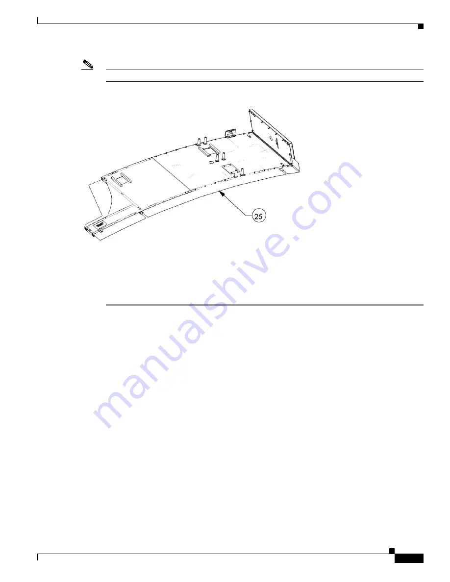
Figure 1-26

Figure 1-26

Attaching the Fabric Sub- Assembly to the Frame

Step 8

Pull the edges of the Fabric Sub- Assembly over the edges of the frame on the narrow side.

Step 9

Place the Fabric Sub- Assembly grommets on the frame studs on the narrow side. Overlap two grommets 
on the studs at the corners of the frame.

Step 10

Place the grommets on the studs following the outer edge of the screen and frame making sure the 
bracket holes align with the curves in the Fabric Sub- Assembly. 

Attaching the Feet Bracket and Leveling Feet to the Frame

This section describes the steps you perform to attach the Feet Bracket and leveling feet to the frameand 
includes the following topics:

Required Parts and Tools, page 33

Attaching the Feet Bracket to the Frame, page 34

Required Parts and Tools

6 M4x 20 Pan Head Phillip Screw 

3 leveling feet

3 foot brackets

1 #2 Phillips screwdriver

Содержание TelePresence 3000

Страница 1: ...wing sections Assembly Overview page 2 Preparing for the Installation page 2 Unpacking page 3 Materials and Tools page 3 Preparing the Display Shelves for the Display and Screens page 8 Attaching the Screen and Shelf Attachment Hardware and Display Frame Brackets page 12 Removing the Projector and Installing the Privacy Panel Cover page 22 Preparing the Speakers page 23 Assembling the Screens page...

Страница 2: ...Weight The following section provides you with the shipping dimensions and weight of the upgrade kit Size of Entire Kit 48 x 48 x 45 5 1220mm x 1220mm x 1156mm Weight of Entire Kit 222 pounds 83Kg Size of Kit Components Facade includes speaker covers 45 75 x 17 75 x 41 1162mm x 451mm x 1041mm 40 inch high definition display 42 25 x 12 x 27 75 1073mm x 305mm x 705mm Speakers 23 x 22 25 x 12 625 584...

Страница 3: ...rame Guide Sub Assembly 1 Part of CTS 3X10FACADE 5 Kick guard Center Tube Sub Assembly 1 Part of CTS 3X10FACADE 6 Left Right kick guard Sub Assembly 2 Part of CTS 3X10FACADE 7 Right Sub Assembly 2 Part of CTS 3X10FACADE 8 Speaker Locating Bracket 4 Part of CTS 3X10FACADE 9 Locating Plate 4 Part of CTS 3X10FACADE 10 Left End Unit Cap 1 Part of CTS 3X10FACADE 11 Right End Unit Cap 1 Part of CTS 3X10...

Страница 4: ...32 3 mm Long Arm Allen wrench 1 Part of CTS 3X10FACADE 33 Gloves 2 pairs Part of CTS 3X10FACADE 34 Left Frame Bracket 2 Part of CTS 3X10FACADE 35 Right Frame Bracket 2 Part of CTS 3X10FACADE 36 Left Center Frame Bracket Assembly 1 Part of CTS 3X10FACADE 37 Right Center Frame Bracket Assembly 1 Part of CTS 3X10FACADE 38 Privacy Panel Cover 1 Part of CTS 3X10FACADE 39 Cable Sheath 1 Part of CTS 3X10...

Страница 5: ...rojector removal and reinstallation of the display shelf and installation of the LCD screen brackets Power drill Phillips drill bit To differentiate between the different screws that are used in this installation see Table 2 The illustrations in the table are close to the actual size of the screws Table 2 Fasteners Used in Installation Procedure Item Number Image and Description Quantity 18 M6 Sho...

Страница 6: ...lePresence Screen Each illustration is keyed numerically to the Materials and Tools list You can refer to the Materials and Tools list to identify the specific screw or bracket being used in an illustration 22 M6 x 16 Pan Head Phillip Screw 2 23 M8 x 16 Pan Head Phillip Screw 4 Table 2 Fasteners Used in Installation Procedure Continued Item Number Image and Description Quantity ...

Страница 7: ...7 OL 23393 01 Figure 1 Exploded View of Screen Frame Components 8 23 12 13 4 5 6 10 3 15 2 9 22 14 19 7 20 1 17 18 21 11 16 27 206941 ...

Страница 8: ...nd includes the following topics Removing the Existing Screen and Speaker Boards page 8 Attaching the Screen and Shelf Attachment Hardware and Display Frame Brackets page 12 Removing the Existing Screen and Speaker Boards This section provides you with the procedure you complete to remove the screen and speaker boards and includes the following topics Required Parts and Tools page 9 Removing the E...

Страница 9: ... of the screen complete the following steps 1 Lower the feet that are at the bottom of the screen to their lowest height by rotating them counter clockwise with the open ended wrench 2 Pull the screen out and away from the display shelves Figure 3 Lowering the Screen Feet For a Screen With a Kick Guard If the screen does not have a kick guard on the bottom of the screen and is completely white det...

Страница 10: ...10 OL 23393 01 Figure 4 Removing the Speaker Boards 207169 ...

Страница 11: ...Remove all speaker board brackets and either the screen clips or locating plate for the screen The top illustration in Figure 5 shows the speaker board brackets The lower illustration shows the clip and the locating plate remove either the clip or the plate depending on your system Note Make a note of the hole location for the clips or plates you use these same holes to install the new plates in S...

Страница 12: ...the following topics Required Parts and Tools page 12 Replacing the Frame Brackets page 12 Required Parts and Tools 2 Phillips screwdriver 4 locating plates 2 left frame brackets 2 right frame brackets 1 left center frame bracket 1 right center frame bracket 1 hanger rod 2 washers M8 screws 2 M6 x 16 screws Replacing the Frame Brackets To replace the frame brackets complete the following steps Ste...

Страница 13: ... PDUs from the cabinets and set them aside a Rotate the cabinet feet clockwise to lower the feet b Remove the screws that attach the cabinet to the display shelf c Slide the cabinet away from the Cisco TelePresence system d Remove the cabinet brackets from the underside of the display shelves Figure 6 Removing the Cabinets 207168 ...

Страница 14: ...3 Attach the diamond shaped shelf bracket to the right side of the table This bracket joins the right display shelf and the right wing tabletop section Figure 7 Attaching the Shelf Bracket to the Display Shelves 206946 20 ...

Страница 15: ...tachment holes as the locating plates or screen clips that you removed during Step 8 in the Removing the Existing Screen and Speaker Boards section on page 8 Note Attach the locating plates so that the locating pin faces the rear of the system as shown in Figure 8 Figure 8 Locating Plate Orientation 206947 ...

Страница 16: ...Step 5 Remove the tilt bracket from the frame assembly This bracket is denoted as callout 47 in Figure 9 Note Save the tilt bracket you attach it to the new frame bracket Figure 9 Removing the Tilt Brackets 207165 47 ...

Страница 17: ...t bracket first Figure 10 shows the right bracket being removed Figure 10 Removing the Frame Bracket Step 7 Attach the new frame bracket underneath the left display shelf You might have to raise or lower the plasma display leveling feet to make sure that the display remains firmly seated on top of the frame bracket Note Do not use the frame brackets that have a blue hinge You attach these brackets...

Страница 18: ...ame brackets under one display shelf the shelf and plasma screen will be unstable and may fall Step 10 Remove the frame bracket on the left side of the center display shelf and replace it with the new frame bracket with the blue hinge Note Attach the bracket so that the hinge is on the outside Tip Use the callouts in Figure 11 to install the correct parts as listed in Table 1 on page 3 Figure 11 A...

Страница 19: ...ning it with its corresponding hole and attaching the washer and one M6 x 16 pan head phillips screw Step 12 Remove and replace the remaining frame bracket on the center display frame Figure 12 Connecting the Display Hanger Rod and Right Side Bracket to the Center Display Frame 206953 14 37 ...

Страница 20: ...20 OL 23393 01 Step 13 Connect the hanger rod to the right frame bracket Figure 13 Connecting the Hanger Rod to the Right Frame Bracket 206954 37 ...

Страница 21: ...21 OL 23393 01 Step 14 Attach the tilt brackets you removed in Step 5 to the new frame brackets Figure 14 Replacing the Tilt Brackets 207166 ...

Страница 22: ...igure 15 Attaching the Speaker Cables to the Codec Removing the Projector and Installing the Privacy Panel Cover This section describes the procedures you take to remove the projector and install the privacy panel cover and includes the following topics Required Parts and Tools page 22 Removing the Projector and Installing the Privacy Panel page 23 Required Parts and Tools 2 Phillips screwdriver 1...

Страница 23: ...remaining four mounting screws Step 6 Remove the projector assembly by sliding the unit to the side until the projector mounting bracket disengages from the loosened mounting screws Note On some Cisco TelePresence models you remove the projector assembly by sliding it to the front rather than the side Step 7 Remove the screws that attach the mounting plate to the projector and remove the plate Ste...

Страница 24: ...ion complete the following steps Step 1 Attach the speaker to the speaker bracket using the M6 shoulder screws Figure 17 Attaching the Speaker to the Speaker Bracket Note Make sure the speaker attachments show through the opening on the speaker locating bracket Tip To ease the fit of the shoulder screws through the rubber bushings you can add a small of silicone grease to the shoulder screws prior...

Страница 25: ...ludes the following topics Assembling the Kick Guards page 26 Assembling the Left Frame page 27 Attaching the Fabric Sub Assembly page 31 Attaching the Feet Bracket and Leveling Feet to the Frame page 33 Attaching the Speakers to the Frame page 36 Assembling the Right Frame page 39 Attaching the End Caps page 39 Caution Do not use power tools during the assembly of the frames and screens The use o...

Страница 26: ... assembly 4 M4 x 12 Pan Head Phillip Screw 2 Phillips screwdriver Assembling the Kick Guard Subassemblies To prepare the kick guards complete the following steps Place the right kick guard sub assembly into the slot of the kick guard middle frame guide sub assembly and assemble them using M4 x 12 Pan Head Phillip Screws Follow the same procedure to assemble the left kick guard sub assembly with ki...

Страница 27: ...cribes the procedures you perform to assemble the left frame and includes the following topics Required Parts and Tools page 27 Assembling the Left Frame page 28 Required Parts and Tools 1 left sub assembly 1 left center sub assembly 1 Left Screen center Bracket Sub Assembly 5 M4 x 12 Pan Head Phillip Screw 1 2 Phillips screwdriver ...

Страница 28: ...assemble the frame complete the following steps Step 1 Align the guides of the left sub assembly with the slots of the left center sub assembly and insert the guides in the slots Figure 1 20 Attaching the Left and Left Center Frame Subassemblies ...

Страница 29: ...part of the left center sub assembly where the guide and slot meet You must be on the rear side of the left frame to insert the screw Step 3 Tighten the screw Step 4 Repeat Step 4through step3 for the bottom of the left frame Figure 1 21 Connecting the Left and Left Center Frame Subassemblies Front View ...

Страница 30: ...30 OL 23393 01 Figure 1 22 Connecting the Left and Left Center Frame Subassemblies Rear View ...

Страница 31: ...creen center Bracket Sub Assembly to the Left Subassembly Attaching the Fabric Sub Assembly This section describes the steps you complete to attach the Fabric Sub Assembly to the frame and includes the following topics Required Parts and Tools page 31 Attaching the Fabric Sub Assembly to the Frame page 32 Required Parts and Tools 1 foam sheet 2 gloves 1 Fabric Sub Assembly 1 left frame ...

Страница 32: ...face Step 3 Put on the gloves that are included with the kit Step 4 Lay the Fabric Sub Assembly flat on the foam sheet Figure 1 24 Fabric Sub Assembly Step 5 Lay the left frame on the Fabric Sub Assembly front aligning the outer edges Figure 1 25 Frame and Fabric Sub Assembly Step 6 Align the bracket holes on the frame with their corresponding curves in the Fabric Sub Assembly Step 7 Locate the ST...

Страница 33: ...t the corners of the frame Step 10 Place the grommets on the studs following the outer edge of the screen and frame making sure the bracket holes align with the curves in the Fabric Sub Assembly Attaching the Feet Bracket and Leveling Feet to the Frame This section describes the steps you perform to attach the Feet Bracket and leveling feet to the frameand includes the following topics Required Pa...

Страница 34: ...34 OL 23393 01 Attaching the Feet Bracket to the Frame Figure 1 27 Attaching the Feet bracket to the Frame ...

Страница 35: ...e kick guard and on the support of the screen Step 12 Place two M4 x 20 screws in their corresponding locations attaching the kick guard to the screen Make sure to place the end studs in the relief hole of the foot bracket sub assembly Figure 1 28 Attaching the Levelling Feet to the Frame ...

Страница 36: ... feet during screen installation Figure 1 29 Lowering the Leveling Feet Step 16 Stand the screen upright on the floor Attaching the Speakers to the Frame This section describes the procedure you perform to attach the speaker to the screen and includes the following topics Required Parts and Tools page 36 Attaching the Speakers to the Frame page 37 Required Parts and Tools 2 speaker assemblies 2 M4...

Страница 37: ...emblies with the frame complete the following steps Step 1 Slightly loosen the 2 screws on the frame and align the key holes of the speaker bracket with the screws Step 2 Tighten the M4 x 12 screws using the 2 Phillips screwdriver Figure 1 30 Attaching the Speaker Assembly to the Screen ...

Страница 38: ...the following steps Step 1 Attach the speaker to the frame using the M6 shoulder screws Figure 1 31 Attaching the Speaker to the Frame Step 2 Repeat Step 1 for attaching one more speaker with the frame Tip To ease the fit of the shoulder screws through the rubber bushings you can add a small amount of silicone grease to the shoulder screws prior to installation ...

Страница 39: ...s page 24 Assembling the Kick Guards page 26 Assembling the Left Frame page 27 Attaching the Fabric Sub Assembly page 31 Attaching the Feet Bracket and Leveling Feet to the Frame page 33 Attaching the Speakers to the Frame page 36 Attaching the End Caps This section includes the steps you complete to attach the end caps to the screen and includes the following topics Required Parts and Tools page ...

Страница 40: ...lace the left end unit cap on the top rounded corner of the left screen aligning it with the holes on the top of the screen Make sure the tab near the bottom of the body of the end unit cap is against the frame providing space between the frame and the end unit cap Figure 1 32 Attaching the Left End Cap to the Frame ...

Страница 41: ...1 Step 2 Place the right end unit cap on the top rounded corner of the right screen aligning it with the holes on the top of the screen and the studs on the side Figure 1 33 Attaching the Right End Cap to the Frame ...

Страница 42: ...to the LCD display and includes the following topics Required Parts and Tools page 42 Attaching the Brackets to the LCD Display page 43 Required Parts and Tools 1 Cisco LCD screen 2 LCD Brackets 4 M8x 16 mm pan head Phillips screws 1 Hanger Rod 2 Washer 2 M6 x 16 Pan Head Phillip Screw 2 Phillips screwdriver ...

Страница 43: ... area of dirt and debris Step 2 Lay the LCD screen flat on the floor face down on top of clean foam or cardboard to make sure you do not scratch the screen Step 3 Attach the LCD mounting brackets to the rear of the LCD screen using four M8 x 16 mm pan head Phillips screws Figure 1 34 Attaching the LCD Mounting Brackets to the LCD Screen ...

Страница 44: ...rts and Tools 1 left Frame 1 right Frame 1 LCD screen 1 HDMI cable 1 open ended wrench Attaching the Screens and Display to the Cisco TelePresence System To attach the screen assembly to the Cisco TelePresence system complete the following steps Step 1 Make sure the PDUs are powered off Step 2 Open the table door and slide the right screen through the door Step 3 Position the screen so that it is ...

Страница 45: ...CD screen and the PDU and connect the HMDI cable between the LCD screen and the codec Make sure the PDU is turned off Step 5 Make sure the blue hinge pieces on the center frame brackets are in the correct up position aligned with the bracket Figure 1 36 Correct Positioning of Hinged Pieced on Center Display Brackets ...

Страница 46: ...ged pieces on the center frame brackets to the down position Figure 1 37 Moving the Hinged Pieces Down on the Center Display Bracket Step 8 Connect the cables for the display by following the diagrams in the Figure 1 44 through Figure 1 46 Note Be sure to connect the serial cable from the auxiliary control unit to the RS232C IN connection of the presentation display the serial connection that is c...

Страница 47: ...erside of the table shelf to the locating plates on the right screen Step 14 Raise the leveling feet on the screen so that the top edge of the screen is snug with the underside of the display shelves Note Do not tighten the leveling feet as you may need to adjust the placement of the screen Figure 1 38 Raising the Leveling Feet Step 15 Repeat Step 12 through Step 14 for the left screen inserting t...

Страница 48: ...letops are not level adjust the leveling feet or move the screen until the tabletops are level Step 19 After completing the final adjustments make sure the locating brackets are still aligned Completing the Assembly This section describes the steps you take to complete the assembly of the screens and display and includes the following topics Required Parts and Tools page 48 Completing the Assembly...

Страница 49: ...s the opposite direction of the right screen Figure 1 40 Placing the Cables into the Cable Sheath Step 3 Walk to the back of the Cisco TelePresence screen and locate the speakers on each side of the LCD screen Step 4 Place one grommet of the LCD back cover on the stud on the speaker locating bracket Note The back cover is the shaded item in the following illustrations Figure 1 41 Placing the LCD B...

Страница 50: ...n and the top of the LCD mounting brackets Figure 1 42 Continuing the Attachment of the LCD Back Cover Step 6 Place the other grommet of the LCD back cover on the stud on the other speaker locating bracket Figure 1 43 Completing Attachment of the LCD Back Cover Step 7 Set up the LCD screen by completing the procedure in the Troubleshooting the Display section on page 51 ...

Страница 51: ...on e Click Start to begin the test Step 3 Turn on the display If the display does not show a test pattern see the Troubleshooting the Display section on page 51 to attempt to fix the problem Step 4 From Cisco TelePresence System Administration click Set LCD Defaults to automatically configure the display for use with the Cisco TelePresence system Note Although the 40 inch display ships with a remo...

Страница 52: ...to the display and into the correct connector on the primary codec Contact Cisco technical support if you are certain that the cabling is correct and power is applied to the system but no image is displayed Test pattern is not displayed Display is set up to receive PC input instead of input from its video cable connector Use the display remote control to configure the display for HD video input If...

Страница 53: ... 44 Cable Routing for Standard Cisco TelePresence System 206986 1 2 1 2 10 100 NETWORK PORTS RESET SERIAL PORTS Presentation display Primary Codec Auxiliary Control Unit Auxiliary Video Out Camera IP Phone Auxiliary network port Network Far Left Far Right Document Camera Center Left Left Codec Right Codec Center Right Display Auxiliary Video In Video In Serial RS232 IN First Row Center Microphone ...

Страница 54: ...re 1 45 Cable Routing for Cisco TelePresence system with Presentation Codec 206987 1 2 1 2 10 100 NETWORK PORTS RESET SERIAL PORTS Presentation display Primary Codec Auxiliary Control Unit Presentation Codec Auxiliary Video Out Camera IP Phone Auxiliary network port Network Document Camera Left Codec Right Codec Display Auxiliary Video In Auxiliary Video In Video out Video In Serial RS232 IN First...

Страница 55: ... external display s Cables for the external displays and document camera are not included with the standard Cisco TelePresence installation Note When you use the audio video extension unit as a video splitter connect port 1 of the Video in connection from the codec and port 4 of the Video out connection to the presentation display Note If you have a presentation codec with an external display use ...

Страница 56: ... Video Expansion Unit External Display Optional Presentation display Document Camera Optional Auxiliary Video Out Camera IP Phone Auxiliary network port Network First Row Center Microphone Document Camera Video In Left Codec Right Codec Display Auxiliary Video In Video In Video In Video Out Video In Audio Expansion Unit Speaker Auxiliary Control Unit Serial 2 Serial 1 Ethernet 1 Ethernet 2 Serial ...

Страница 57: ...57 OL 23393 01 ...

Страница 58: ...58 OL 23393 01 ...

Отзывы: