Cisco PIX-515E Скачать руководство пользователя страница 13

13

Step 2: Configure Address Translations on Private Networks

Network Address Translation (NAT) replaces the source IP addresses of network traffic exchanged 
between two security appliance interfaces. This translation prevents the private address spaces from 
being exposed on public networks and permits routing through the public networks. Port Address 
Translation (PAT) is an extension of the NAT function that allows several hosts on the private 
networks to map into a single IP address on the public network. PAT is essential for small and medium 
businesses that have a limited number of public IP addresses available to them.

To configure NAT between the inside interface and the DMZ interface for the inside HTTP client, 
complete the following steps starting from the main ASDM page:

1.

Click the Configuration button at the top of the ASDM window.

2.

Choose the NAT feature on the left side of the ASDM window. 

3.

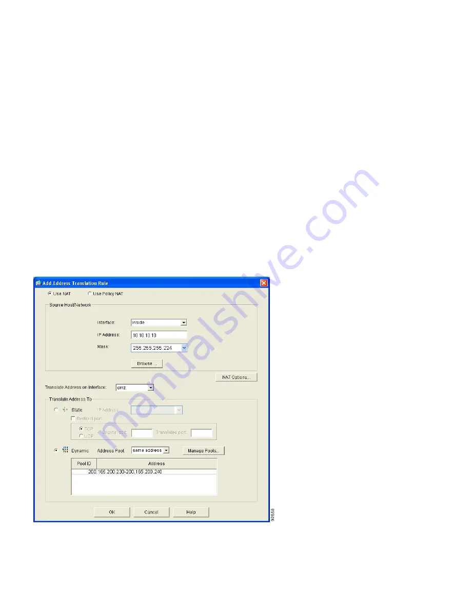
Click the Translation Rules radio button, and then click the Add button at the right side of the 
ASDM page. The Add Address Translation Rule window appears.

4.

In the Add Address Translation Rule window, make sure that the Use NAT radio button is 
selected, and then choose the inside interface from the drop-down menu.

Содержание PIX-515E

Страница 1: ...E Security Appliance Quick Start Guide 1 Verifying the Package Contents 2 Installing the PIX 515E Security Appliance 3 Configuring the Security Appliance 4 Common Configuration Scenarios 5 Optional Maintenance and Upgrade Procedures ...

Страница 2: ...remote management capabilities in an easy to deploy high performance solution About this document This document describes how to install and configure the security appliance for use in a VPN or DMZ deployment When you have completed the procedures outlined in this document the security appliance will be running a basic VPN or DMZ configuration The document provides only enough information to get t...

Страница 3: ... PIX 515E PC terminal adapter 74 0495 01 Documentation Blue console cable 72 1259 01 Yellow Ethernet cable 72 1482 01 C i s c o P I X S e c u r i t y A p p l i a n c e P r o d u c t C D DO NOT INSTALL INTERFACE CARDS WITH POWER APPLIED Link FDX FDX 100 Mbps Link 100 Mbps FAILOVER PIX 515E CONSOLE 10 100 ETHERNET 1 10 100 ETHERNET 0 Failover serial cable 74 1213 01 Mounting brackets 700 01170 02 AO...

Страница 4: ...is to the equipment rack Step 2 Use one of the provided yellow Ethernet cables 72 1482 01 to connect the outside 10 100 Ethernet interface Ethernet 0 to a DSL modem cable modem router or switch Step 3 Use the other provided yellow Ethernet cable 72 1482 01 to connect the inside 10 100 Ethernet interface Ethernet 1 to a switch or hub Step 4 Connect one end of the power cable to the rear of the PIX ...

Страница 5: ...de interface is configured with a default DHCP address pool This configuration enables a client on the inside network to obtain a DHCP address from the security appliance in order to connect to the appliance Administrators can then configure and manage the security appliance using ASDM The outbound interface is configured to deny all inbound traffic through the outside interface This configuration...

Страница 6: ...ddition to the ASDM web configuration tool you can configure the security appliance by using the command line interface For more information refer to the Cisco Security Appliance Command Line Configuration Guide and the Cisco Security Appliance Command Reference Using the Startup Wizard ASDM includes a Startup Wizard to simplify the initial configuration of your security appliance With a few steps...

Страница 7: ...ction is established the LINK LED on the Ethernet 1 interface of the security appliance and the corresponding LINK LED on the switch or hub will become solid green Step 4 Launch the Startup Wizard a On the PC connected to the switch or hub launch an Internet browser b In the address field of the browser enter this URL https 192 168 1 1 Note The security appliance ships with a default IP address of...

Страница 8: ...common to most DMZ implementations that use the security appliance The web server is on the DMZ interface and HTTP clients from both the inside and outside networks are able to access the web server securely In the Figure 2 an HTTP client 10 10 10 10 on the inside network initiates HTTP communications with the DMZ web server 30 30 30 30 HTTP access to the DMZ web server is provided for all clients...

Страница 9: ...hat you want to make available to clients on the public network in this scenario a web server External IP addresses to be used for servers inside the DMZ Clients on the public network will use the external IP address to access the server inside the DMZ Client IP address to substitute for internal IP addresses in outgoing traffic Outgoing client traffic will appear to come from this address so that...

Страница 10: ...Pools window appears allowing you to add or edit global address pools Note For most configurations global pools are added to the less secure or public interfaces 5 In the Manage Global Address Pools window a Choose the dmz interface b Click the Add button The Add Global Pool Item window appears ...

Страница 11: ... Enter a unique Pool ID For this scenario the Pool ID is 200 e Click the OK button to go back to the Manage Global Address Pools window Note You can also choose Port Address Translation PAT or Port Address Translation PAT using the IP address of the interface if there are limited IP addresses available for the DMZ interface 7 In the Manage Global Address Pools window a Choose the outside interface...

Страница 12: ...ick the OK button The configuration should be similar to the following 9 Confirm that the configuration values are correct then a Click the OK button b Click the Apply button in the main window Note Because there are only two public IP addresses available with one reserved for the DMZ server all traffic initiated by the inside HTTP client exits the security appliance using the outside interface IP...

Страница 13: ...T is essential for small and medium businesses that have a limited number of public IP addresses available to them To configure NAT between the inside interface and the DMZ interface for the inside HTTP client complete the following steps starting from the main ASDM page 1 Click the Configuration button at the top of the ASDM window 2 Choose the NAT feature on the left side of the ASDM window 3 Cl...

Страница 14: ... Dynamic radio button in the Translate Address To to section 9 Choose 200 from the Address Pools drop down menu for the appropriate Pool ID 10 Click the OK button 11 A pop up window displays asking if you want to proceed Click the Proceed button 12 On the NAT Translation Rules page verify that the displayed configuration is accurate 13 Click the Apply button to complete the configuration changes T...

Страница 15: ...T feature on the left side of the ASDM window 2 Click the Translation Rules radio button Then click the Add button at the right side of the page 3 Choose the outside dmz interface from the drop down menu of interfaces 4 Enter the IP address 30 30 30 30 of the web server or click the Browse button to select the server 5 Choose 255 255 255 255 from the Mask drop down menu Then click the Static radio...

Страница 16: ... table choose Add 2 In the Add Rule window a Under Action choose permit from the drop down menu to allow traffic through the security appliance b Under Source Host Network click the IP Address radio button c Choose outside from the Interface drop down menu d Enter the IP address of the Source Host Network information Use 0 0 0 0 to allow traffic originating from any host or network e Under Destina...

Страница 17: ...r 80 a Click the TCP radio button under Protocol and Service b Under Source Port choose equal to from the Service drop down menu c Click the button labeled with ellipses scroll through the options and choose Any d Under Destination Port choose equal to from the Service drop down menu e Click the button labeled with ellipses scroll through the options and select HTTP ...

Страница 18: ... button Note Although the destination address specified above is the private address of the DMZ web server 30 30 30 30 HTTP traffic from any host on the Internet destined for 209 165 156 11 is permitted through the security appliance The address translation 30 30 30 30 209 165 156 11 allows the traffic to be permitted h Click the Apply button in the main window The configurations should display as...

Страница 19: ... a VPN connection such as the one in the above illustration requires you to configure two security appliances one on each side of the connection ASDM provides an easy to use configuration wizard to guide you quickly through the process of configuring a site to site VPN in a few simple steps Step 1 Configure the PIX security appliance at the first site Configure the security appliance at the first ...

Страница 20: ...to Site VPN option connects two IPSec security gateways which can include security appliances VPN concentrators or other devices that support site to site IPSec connectivity b From the drop down menu choose outside as the enabled interface for the current VPN tunnel c Click the Next button to continue ...

Страница 21: ...tion that you want to use by performing one of the following To use a pre shared key for authentication for example CisCo click the Pre Shared Key radio button and enter a pre shared key which is shared for IPSec negotiations between both security appliances Note When you configure the PIX 2 at the remote site the VPN peer is PIX 1 Be sure to enter the same Pre shared Key CisCo that you use here T...

Страница 22: ...nnels between two peers To specify the IKE policy complete the following steps 1 Select the Encryption DES 3DES AES Authentication algorithms MD5 SHA and the Diffie Hellman group 1 2 5 used by the security appliance during an IKE security association Note When configuring PIX 2 enter the exact values for each of the options that you chose for PIX 1 Encryption mismatches are a common cause of VPN t...

Страница 23: ...etworks Identify hosts and networks at the local site to be allowed to use this IPSec tunnel to communicate with the remote site peers The remote site peers will be specified in a later step Add or remove hosts and networks dynamically from the Selected panel by clicking on the or buttons respectively In the current scenario traffic from Network A 10 10 10 0 is encrypted by SA 1 and transmitted th...

Страница 24: ... that you want to have access to the tunnel 6 Click the Next button to continue Step 6 Specify Remote Hosts and Networks Identify hosts and networks at the remote site to be allowed to use this IPSec tunnel to communicate with the local hosts and networks you identified in Step 5 Add or remove hosts and networks dynamically from the Selected panel by clicking on the or buttons respectively In the ...

Страница 25: ... choosing one location from the Interface drop down menu 3 Enter the IP address and mask 4 Click Add 5 Repeat step 1 through step 5 for each host or network that you want to have access to the tunnel 6 Click the Next button to continue Note When configuring PIX 2 ensure that the values are correctly entered The remote network for PIX 1 is the local network for PIX 2 and the reverse ...

Страница 26: ...n click Finish to complete the Wizard and apply the configuration changes to the security appliance Note When configuring PIX 2 enter the same values for each of the options that you selected for PIX 1 Encryption and algorithm mismatches are a common cause of VPN tunnel failures and can slow down the process This concludes the configuration process for PIX 1 ...

Страница 27: ...gy such as secure remote management SSH ASDM and so on site to site VPN and remote access VPN Enabling the license requires an encryption license key If you ordered your security appliance with a DES or 3DES AES license the encryption license key comes with the security appliance If you did not order your security appliance with a DES or 3DES AES license and would like to purchase one now the encr...

Страница 28: ...p 3 pix config activation key activation 5 tuple key Updates the encryption activation key by replacing the activation 4 tuple key variable with the activation key obtained with your new license The activation 5 tuple key variable is a five element hexadecimal string with one space between each element An example is 0xe02888da 0x4ba7bed6 0xf1c123ae 0xffd8624e The 0x is optional all values are assu...

Страница 29: ... Locate the blue console cable from the accessory kit The blue console cable assembly consists of a null modem cable with RJ 45 connectors and a DB 9 connector Step 2 Connect the RJ 45 connector to the PIX 515E security appliance console port and connect the other end to the serial port connector on your computer See Figure 4 Step 4 hostname config configure factory default inside_ip_address addre...

Страница 30: ...single port Ethernet circuit boards installed in the auxiliary assembly on the left of the unit at the rear the circuit boards are numbered top to bottom so that the top circuit board is Ethernet 2 and the bottom circuit board is Ethernet 3 99547 RJ 45 to DB 9 serial cable null modem PC terminal adapter DB 9 CONSOLE 10 100 ETHERNET 0 0 FDX Link 100 Mbps FAILOVER PIX 515 Console port RJ 45 DO NOT I...

Страница 31: ...etwork cables to the interface ports Starting from the top left the connectors are Ethernet 2 Ethernet 3 Ethernet 4 and Ethernet 5 The maximum number of allowed interfaces is six with an unrestricted license Note Do not add a single port circuit board in the extra slot below the four port circuit board because the maximum number of allowed interfaces is six Step 4 Power on the unit from the switch...

Страница 32: ... active unit Off Off when the unit is in standby mode If failover is not enabled this light is off NETWORK Green Flashing On when at least one network interface is passing traffic POWER ACT NETWORK 97779 97784 DO NOT INSTALL INTERFACE CARDS WITH POWER APPLIED CONSOLE 10 100 ETHERNET 0 ACT LINK LINK 100 Mbps ACT 100 Mbps FAILOVER USB 10 100 ETHERNET 1 PIX 515 10 100BaseTX ETHERNET 0 RJ 45 10 100Bas...

Страница 33: ...ical resources These sections explain how to obtain technical information from Cisco Systems Cisco com You can access the most current Cisco documentation at this URL http www cisco com univercd home home htm You can access the Cisco website at this URL http www cisco com You can access international Cisco websites at this URL http www cisco com public countries_languages shtml ...

Страница 34: ...t this URL http www cisco com univercd cc td doc es_inpck pdi htm You can order Cisco documentation in these ways Registered Cisco com users Cisco direct customers can order Cisco product documentation from the Ordering tool http www cisco com en US partner ordering Nonregistered Cisco com users can order documentation through a local account representative by calling Cisco Systems Corporate Headq...

Страница 35: ...t_rss_feed html Reporting Security Problems in Cisco Products Cisco is committed to delivering secure products We test our products internally before we release them and we strive to correct all vulnerabilities quickly If you think that you might have identified a vulnerability in a Cisco product contact PSIRT Emergencies security alert cisco com Nonemergencies psirt cisco com Tip We encourage you...

Страница 36: ...uct serial number before submitting a web or phone request for service You can access the CPI tool from the Cisco Technical Support Website by clicking the Tools Resources link under Documentation Tools Choose Cisco Product Identification Tool from the Alphabetical Index drop down list or click the Cisco Product Identification Tool link under Alerts RMAs The CPI tool offers three search options by...

Страница 37: ...ant aspects of your business operation are negatively affected by inadequate performance of Cisco products You and Cisco will commit full time resources during normal business hours to resolve the situation Severity 3 S3 Operational performance of your network is impaired but most business operations remain functional You and Cisco will commit resources during normal business hours to restore serv...

Страница 38: ...ow they can use technology to increase revenue streamline their business and expand services The publication identifies the challenges facing these companies and the technologies to help solve them using real world case studies and business strategies to help readers make sound technology investment decisions You can access iQ Magazine at this URL http www cisco com go iqmagazine Internet Protocol...

Страница 39: ...39 ...

Страница 40: ... Cisco Systems has more than 200 offices in the following countries Addresses phone numbers and fax numbers are listed on the C i s c o W e b s i t e a t w w w c i s c o c o m g o o f f i c e s Argentina Australia Austria Belgium Brazil Bulgaria Canada Chile China PRC Colombia Costa Rica Croatia Cyprus Czech Republic Denmark Dubai UAE Finland France Germany Greece Hong Kong SAR Hungary India Indon...

Страница 41: ...41 ...

Страница 42: ...42 ...

Отзывы: