3-2
PA-5EFL Ethernet 10Base-FL Port Adapter Installation and Configuration
OL-3495-02
Chapter 3 Removing and Installing Port Adapters
Online Insertion and Removal
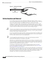
Figure 3-1
Handling a Port Adapter
Online Insertion and Removal
Several platforms support online insertion and removal (OIR) of port adapters; therefore, you do not
have to power down routers when removing and replacing a PA-5EFL port adapter on Cisco 7100 series
routers, Cisco 7200 series routers, Cisco uBR7246 series routers, or the Cisco 7301 router.
Although the VIP supports online insertion and removal, individual port adapters do not. To replace
port adapters, you must first remove the VIP from the chassis and then install or replace port adapters as
required. If a blank port adapter is installed on the VIP in which you want to install a new port adapter,
you must first remove the VIP from the chassis and then remove the blank port adapter.
Caution
To prevent system problems, do not remove port adapters from the VIP motherboard or attempt to install
other port adapters on the motherboard when the system is operating. To install or replace port adapters,
first remove the VIP from its interface processor slot.
It is wise to gracefully shut down the system before removing a port adapter that has active traffic moving
through it. Removing a module while traffic is flowing through the ports can cause system disruption.
Once the module is inserted, the ports can be brought back up.
Note
As you disengage the module from the router or switch, online insertion and removal (OIR)
administratively shuts down all active interfaces in the module.
OIR allows you to install and replace modules while the router is operating; you do not need to notify
the software or shut down the system power, although you should not run traffic through the module you
are removing while it is being removed. OIR is a method that is seamless to end users on the network,
maintains all routing information, and preserves sessions.
The following is a functional description of OIR for background information only; for specific
procedures for installing and replacing a module in a supported platform, refer to the
“Port Adapter
Removal and Installation” section on page 3-4
.
Each module has a bus connector that connects it to the router. The connector has a set of tiered pins in
three lengths that send specific signals to the system as they make contact with the module. The system
assesses the signals it receives and the order in which it receives them to determine if a module is being
removed from or introduced to the system. From these signals, the system determines whether to
reinitialize a new interface or to shut down a disconnected interface.
H6420
Metal carrier
Printed circuit board


