1-64
Cisco ONS 15454 DWDM Procedure Guide, R8.0
78-17704-02
Chapter 1 Install the Shelf and Common Control Cards
NTP- G12 Install and Close the FMEC Cover (ETSI Only)
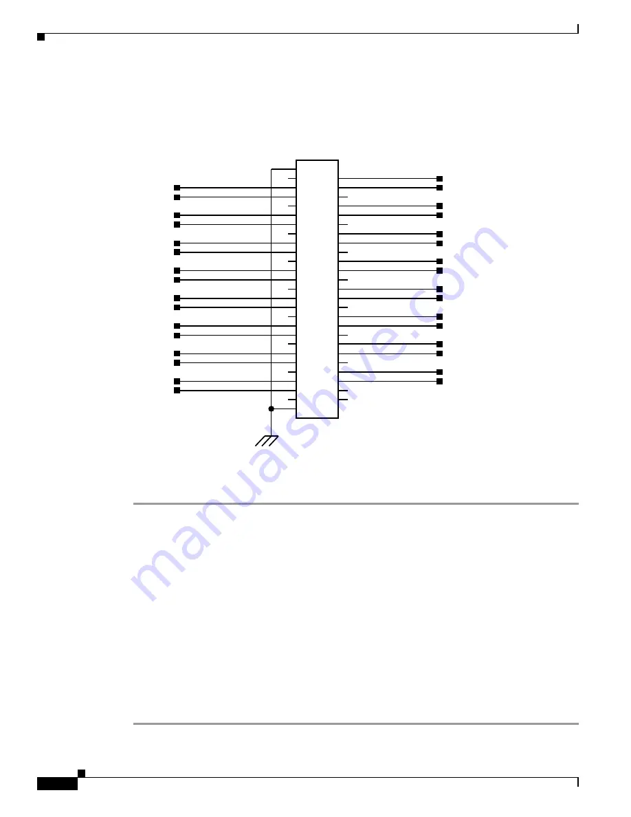
illustrates the alarm output connectors.
Figure 1-28
Alarm Output Connector
Step 4
Continue with the
“NTP-G13 Install the Rear Cover (ANSI Only)” procedure on page 1-65
Stop. You have completed this procedure.
NTP-G12 Install and Close the FMEC Cover (ETSI Only)
Step 1
Insert the cover carefully onto the left pin of the hinge (
NO_5
XREF=7
COM_5
XREF=7
NO_3
XREF=7
COM_3
XREF=7
COM_14
XREF=7
NO_14
XREF=7
XREF=7
COM_12
NO_12
XREF=7
COM_10
XREF=7
NO_10
XREF=7
COM_8
XREF=7
NO_8
XREF=7
COM_6
XREF=7
NO_6
XREF=7
COM_4
XREF=7
NO_4
XREF=7
COM_2
XREF=7
NO_1
XREF=7
NO_2
XREF=7
COM_0
XREF=7
NO_0
XREF=7
NO_15
XREF=7
COM_15
XREF=7
NO_13
XREF=7
COM_13
XREF=7
COM_1
XREF=7
NO_11
XREF=7
COM_11
XREF=7
NO_9
XREF=7
COM_9
XREF=7
NO_7
XREF=7
COM_7
XREF=7
Connector
Alarm Output
GND1
GND2
1
10
11
12
13
14
15
16
17
18
19
2
20
21
22
23
24
25
26
27
28
29
3
30
31
32
33
34
35
36
37
38
39
4
40
41
42
43
44
45
46
47
48
49
5
50
6
7
8
9
51
52
P4
79876
Purpose
This procedure installs and closes the ONS 15454 ETSI FMEC cover.
Tools/Equipment
#2 Phillips Dynamometric screwdriver
Medium slot-head screwdriver
Small slot-head screwdriver
Prerequisite Procedures
NTP-G4 Open and Remove the FMEC Cover (ETSI Only), page 1-25
Required/As Needed
Required
Onsite/Remote
Onsite
Security Level
None


