Installing DC Input Power Cables
This section describes how to connect the DC input power cables and install DC terminal block covers. The
DC terminal block cover is one piece that covers all four DC connections per tray.
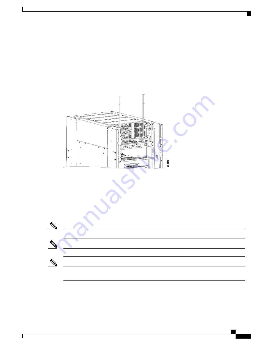
The following figure shows the DC input power cabling on the rear of the power enclosure. In this example,
the cabling for the four power trays all route to the right.
Figure 37: DC Input Power Cabling
Prerequisites
•
Installing the Exterior Cosmetics, on page 20
•
Installing an AC or DC Power Tray, on page 18
•
Installing an AC or DC Power Module , on page 46
Before installing the cabling on the power tray, ensure that the input power cables are not energized.
Note
Ensure that there is a readily accessible disconnect device incorporated in the building's installation wiring.
Note
The circuit breaker and fuse lockout procedures should follow the rules and regulations in the National
Electrical Code (NEC) and any local codes.
Note
Required Tools and Equipment
•
DC power cables
Cisco Network Convergence System 6000 Fabric Card Chassis Hardware Installation Guide
55
Installing the Power Components
Installing DC Input Power Cables


