Step 8
Firmly push on the fan tray handle to seat the fan tray connector in the FCC connector. When the fan tray is completely
seated, the fan tray faceplate flanges meet the rear side of the FCC.
All electrical and control line connections are made automatically when the connectors mate. The LED will
light when the fan tray is inserted. The LED is yellow initially, until the system has confirmed it is functioning
correctly.
Note
Step 9
Tighten the captive screws on each side of the fan tray faceplate.
Replacing the Air Filter
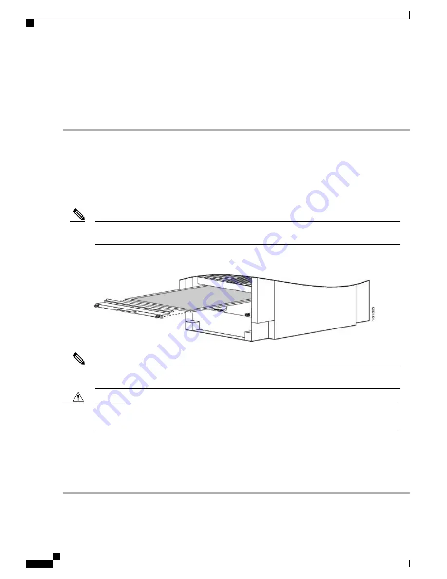
This section describes how to install an air filter in the Cisco NCS 6000 FC. The following figure shows the
FCC air filter. The air filter is located on the front of the FCC as shown in
Figure 1: Front View of the Cisco
.
We recommend that you change the air filter every three months. The filter is sold in packs of five through
Cisco (PID NC6-5XFILTER=).
Note
Figure 68: FCC Air Filter
A lattice of wire exists on both sides of the filter material with an arrow denoting airflow direction and a
pair of sheet metal straps on the downstream side of the filter assembly.
Note
Never operate the FCC without an air filter. Operating the FCC without a filter for an extended time can
result in damage to the FCC hardware.
Caution
Steps
To replace the air filter, follow these steps:
Step 1
Remove the filter you are replacing.
Cisco Network Convergence System 6000 Fabric Card Chassis Hardware Installation Guide
114
Removing and Replacing Chassis Components
Replacing the Air Filter


