background image


5-71

Cisco MGX 8800/8900 Series Hardware Installation Guide

Releases 2 - 5.2, Part Number OL-4545-01, Rev. H0, May 2006

Chapter 5

Installing the Cisco MGX Switch or Gateway

Installing the MGX 8950 Switch

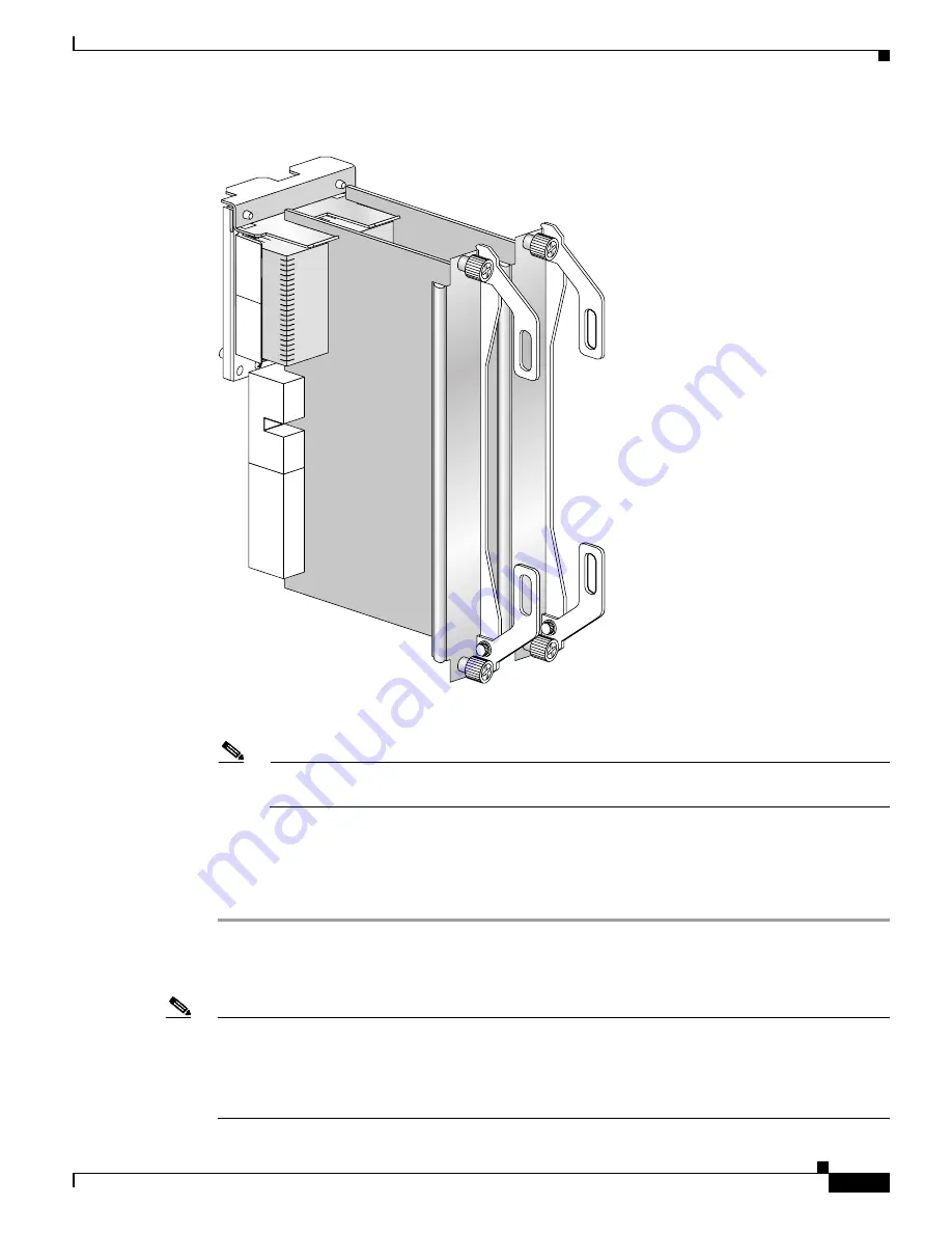
Figure 5-43

Two Back Cards in the MGX-APS-CON-8950Connector

Step 4

Position the APS assembly in the appropriate card slots.

Note

The extractor levers must be closed (flush with the vertical edge of the back cards, as shown in 

Figure 5-13

 and 

Figure 5-14

), or the APS assembly cannot slide properly into the chassis.

Step 5

Slide the APS assembly all the way into the slot until it is properly seated in the backplane. The 
faceplates of the back cards are flush with the card cage when the APS assembly is properly seated.

Step 6

Tighten the captive screws on the back cards with the appropriate screwdriver. If you have difficulty 
inserting the captive screws, verify that the screws are aligned with the holes.

Reinstall the Back Cards

Note

All cards must be fully seated in the chassis. When installing the back card, apply even pressure to the 
top and bottom of the faceplate to make sure that the card is fully seated.

The card should slide in and out with only slight friction on the adjacent board’s EMI gaskets. Do not 
force the card. Investigate any binding.

149631

Содержание MGX 8800 Series

Страница 1: ...Inc 170 West Tasman Drive San Jose CA 95134 1706 USA http www cisco com Tel 408 526 4000 800 553 NETS 6387 Fax 408 526 4100 Cisco MGX 8800 8900 Series Hardware Installation Guide Releases 2 0 5 2 May 2006 Text Part Number OL 4545 01 Rev H0 ...

Страница 2: ...ce by using one or more of the following measures Turn the television or radio antenna until the interference stops Move the equipment to one side or the other of the television or radio Move the equipment farther away from the television or radio Plug the equipment into an outlet that is on a different circuit from the television or radio That is make certain the equipment and the television or r...

Страница 3: ...eleases 37 Related Documentation 38 User Guide Order of Use 38 User Guide Titles and Descriptions 39 Obtaining Documentation 50 Cisco com 50 Product Documentation DVD 50 Ordering Documentation 51 Documentation Feedback 51 Cisco Product Security Overview 51 Reporting Security Problems in Cisco Products 52 Obtaining Technical Assistance 52 Cisco Technical Support Documentation Website 52 Submitting ...

Страница 4: ... 8850 PXM45 and MGX 8850 B PXM45 Slot Assignments 22 MGX 8850 and MGX 8850 B System Hardware Components 23 AC Power Supply Tray 25 Air Intake Plenum 27 APS Assembly 28 DC Power Entry Module 30 Exhaust Plenum 32 Lower and Upper Fan Trays 32 MGX 8850 B Redundancy Connectors 33 Cisco MGX 8950 Switch 34 MGX 8950 Switch Overview 34 MGX 8950 Card Compartment 36 MGX 8950 Slot Assignments 36 MGX 8950 Card...

Страница 5: ...re Components 66 AC Power Supply Tray 68 Air Intake Plenum 70 APS Assembly 71 DC Power Entry Module PEM 72 Exhaust Plenum Fan Tray 73 MGX 8880 Redundancy Connector 73 C H A P T E R 2 Illustrated Card List for MGX Switches and the MGX 8880 Media Gateway 1 How to Use the Illustrated Card List 1 Card Naming Conventions 1 Card Organization 1 Finding the Latest Card Information 1 MGX 8850 PXM45 or MGX ...

Страница 6: ...ions 36 MPSM 8 T1E1 38 MPSM T3E3 155 39 MPSM 16 T1E1 42 PXM1E 45 Module Configurations 48 Faceplate Features 50 PXM45 57 PXM45 Support on MGX 8850 PXM45 or MGX 8850 B PXM45 57 PXM45 Support on MGX 8950 58 Faceplate Features 59 Module Configurations 61 RPM PR 62 Faceplate Features 64 Module Configurations 65 RPM XF 65 Faceplate Features 67 Module Configurations 68 SRM 68 SRM 3T3 C 69 SRME 71 SRME B...

Страница 7: ...92 Back Cards for MGX 8950 Switches 93 Back Cards for MGX 8830 Switches 95 Back Cards for MGX 8880 Media Gateway 96 12IN1 8S 98 BNC 2E3 99 BNC 2T3 100 BNC 3 T3E3 101 BNC 3T3 M 102 MCC 8 155 103 MCC 16 E1 104 MCC 16 E1 1N 104 MGX 1GE 106 MGX 2GE 108 MGX 1OC12POS IR 109 MGX 2OC12POS IR 110 MGX RJ45 5 ETH 111 MGX RJ48 8E1 112 MGX XF UI 113 MGX XF UI B 114 MMF 4 155 C 116 MMF 8 155 MT and MMF 8 155 MT...

Страница 8: ...MFIR 8 155 LC B 146 SMFLR 1 2488 and SMFLR 1 2488 B 147 SMFLR 1 622 C 148 SMFLR 2 622 and SMFLR 2 622 B 149 SMFLR 4 155 C 150 SMFLR 8 155 LC and SMFLR 8 155 LC B 151 SMFSR 1 2488 and SMFSR 1 2488 B 152 SMFSR 1 9953 153 SMFXLR 1 2488 and SMFXLR 1 2488 B 154 STM1 EL 1 155 T3E3 155 156 VXSM BC 4 155 158 VXSM BC 24 T1E1 159 VXSM BC 3T3 160 VXSM R BC 160 C H A P T E R 3 Preparing for Installation 1 Saf...

Страница 9: ...ements 17 AC Power 18 DC Power 19 Power Consumption Calculation Tables 20 Required Tools and Equipment 25 Site Requirements for the MGX 8950 Switch 28 Environmental Requirements 29 Seismic Anchoring 29 Shock 29 Vibration 30 Space 30 Temperature Altitude and Humidity 32 Ventilation 33 Power Requirements 35 AC Power 36 DC Power 37 Power Consumption Calculation Tables 37 Required Tools and Equipment ...

Страница 10: ...R 4 Planning for Card Redundancy Line Redundancy and Bulk Distribution 1 Planning Standalone and Redundant Card Configurations 3 Standalone Card Configuration Guidelines 4 1 1 Redundant Card Configuration Guidelines 5 Preconfigured Redundancy PXM and SRM 6 Configured 1 1 Card Redundancy 8 1 N Redundant Card Configuration Guidelines Except RPM 8 1 N Redundancy without Bulk Distribution 9 1 N Redund...

Страница 11: ...ck Space 12 Prepare for Rack Installation 14 Install the AC Power Supply Tray 17 Install the Air Intake Plenum 20 Install the Lower Fan Tray 20 Install the MGX 8850 or MGX 8850 B Switch without a Mechanical Lift 21 Install the MGX 8850 or MGX 8850 B Switch with a Mechanical Lift 30 Install the Upper Fan Tray 32 Install the Exhaust Plenum 32 Install the DC PEM s 33 Install the Cable Management Asse...

Страница 12: ...witch 80 Connect the DC PEM to the MGX 8950 Switch 84 Connect the Back Cards 88 Connect the Console Port 89 Connect Power to the MGX 8950 Switch 90 Connect the External Clock 95 Connect the Alarms 95 Connect the MP Connection 95 Connect the LAN1 2 Ports 96 Verify EMI Compliance 97 Installing the MGX 8830 or MGX 8830 B Switch 98 Installation Checklist 99 Installation Procedures 101 Install Stabilit...

Страница 13: ...ry Module with Power On 2 Removing and Installing the Double Height Front Cards 4 Remove the Double Height Front Cards 5 How Most Card Levers Work 5 How VXSM Card Levers Work 5 Install the Double Height Front Cards 7 Removing and Installing the Single Height Front Cards 8 Remove the Single Height Front Cards 8 Install the Single Height Front Cards 9 Removing and Installing the Back Cards 9 Remove ...

Страница 14: ...pecifications 7 RPM XF Specifications 8 SRM Specifications 8 A P P E N D I X B Cable Specifications 1 Notes about Cables and Connectors 1 Cable and Connector Naming Conventions 2 Cable Lengths 2 Standard Cisco MGX 8850 PXM1E PXM45 MGX 8850 B and MGX 8880 Cables 2 Standard Cisco MGX 8950 Cables 3 Control and Clock Cabling 3 Maintenance and Control Ports 3 Procedure to Connect a Modem to the Mainten...

Страница 15: ... 14 Y Cables for MGX 8950 15 Trunk Cabling 16 T3 Trunk Cabling 16 E3 Trunk Cabling 16 Frame Relay Cabling 17 T1 Cabling 17 E1 Cabling 19 MGX 12IN1 S8 Back Card Cables 19 MGX SCSI2 2HSSI B Port Connectors 22 VXSM 24 T1 E1 BC Connectors 22 Illustrated Cable Guide 25 List of Cables by Front and Back Card Type 25 List of Cables Illustrated in this Appendix 37 CAB MMF LC 38 CAB MMF LC Y 38 CAB RBBN 16 ...

Страница 16: ... May 2006 Bonding and Grounding MGX 8800 or MGX 8900 Series Chassis in a Rack 9 Wiring a Mixed Ground System with Redundant Supplies 9 Conductor Characteristics for Carrying Current and Ensuring Low Voltage Drops 11 A P P E N D I X D Guide to Transceivers SFPs Used with MGX Back Cards 1 G L O S S A R Y I N D E X ...

Страница 17: ...plate 26 Figure 1 12 Air Flow through the MGX 8850 or MGX 8850 B System 27 Figure 1 13 MGX 8850 APS CON 28 Figure 1 14 APS Assembly Example for MGX 8850 MGX 8850 APS CON 29 Figure 1 15 DC PEM Faceplate 31 Figure 1 16 DC PEMs Installed in Back of the Air Intake Module 31 Figure 1 17 Fan Tray Rear View 32 Figure 1 18 RCON 1TO5 8850 RCON Connector 33 Figure 1 19 RCON 1TO3 8850 RCON Connector 34 Figur...

Страница 18: ...880 Media Gateway Fully Configured with VXSM OC 3 STM 1 63 Figure 1 46 Hardware Component Locations for a Cisco MGX 8880 Media Gateway Front View 67 Figure 1 47 Optional AC Power Supply Tray 68 Figure 1 48 AC Power Supply Faceplate 69 Figure 1 49 Air Flow through the Cisco MGX 8880 System 70 Figure 1 50 APS Assembly Example for MGX 8880 71 Figure 1 51 DC PEM Faceplate 72 Figure 1 52 DC PEMs Instal...

Страница 19: ...gure 2 26 PXM1E COMBO Faceplate PXM1E T3E3 155 56 Figure 2 27 PXM45 and PXM45 B Faceplate 59 Figure 2 28 PXM45 C Faceplate 60 Figure 2 29 RPM PR Faceplate 64 Figure 2 30 RPM XF Faceplate 67 Figure 2 31 SRM 3T3 C Faceplate 70 Figure 2 32 SRME Faceplate 72 Figure 2 33 Card Set Redundancy Configuration SRM Cards 74 Figure 2 34 1 1 Card and APS Line Redundancy Configuration SRM Cards 74 Figure 2 35 SR...

Страница 20: ...XM HD Faceplate 119 Figure 2 63 PXM UI S3 Faceplate 121 Figure 2 64 PXM UI S3 B Faceplate 122 Figure 2 65 RBBN 16 T1E1 Faceplate 124 Figure 2 66 RBBN 16 T1E1 1N Faceplate 125 Figure 2 67 RED 16 T1E1 126 Figure 2 68 RJ45 4E B Faceplate 127 Figure 2 69 RJ45 FE Faceplate 128 Figure 2 70 RJ48 8E1 and R RJ48 8E1 Faceplates 129 Figure 2 71 RJ48 8T1 and R RJ48 8T1 Faceplates 130 Figure 2 72 MGX SCSI2 2HS...

Страница 21: ...igure 3 2 Damaged Connectors on Card 9 Figure 3 3 MGX 8850 or MGX 8850 B Switch Components 14 Figure 3 4 Air Flow Through Intake and Exhaust Vents for the MGX 8850 or MGX 8850 B Switch 16 Figure 3 5 Schematic of AC Plug Wiring 19 Figure 3 6 MGX 8950 Switch Components 31 Figure 3 7 Air Flow Through Intake and Exhaust Vents for the MGX 8950 Switch 34 Figure 3 8 Schematic of AC Plug Wiring 36 Figure ...

Страница 22: ... Front View 16 Figure 5 9 Removing an AC Power Supply 18 Figure 5 10 AC Power Supply Tray Front View 19 Figure 5 11 Lower Fan Tray Air Flow Direction 21 Figure 5 12 Front Card Extractor Lever 23 Figure 5 13 Connecting the Back Card to the MGX 8850 APS CON Connector 26 Figure 5 14 Two Back Cards in the MGX 8850 APS CON Connector 27 Figure 5 15 DC PEMs Installed Behind the Air Intake Plenum on MGX 8...

Страница 23: ...s Installed Behind the Air Intake Plenum 77 Figure 5 45 Cable Management Assembly at Back of System 78 Figure 5 46 Fan Power Cable 79 Figure 5 47 Fan Power Connections AC Powered Node Shown 80 Figure 5 48 Interconnect Cable for AC 81 Figure 5 49 AC Interconnect Cable Connections for Primary and Secondary Power Supplies 83 Figure 5 50 Interconnect Power Connections for AC 84 Figure 5 51 Cable Assem...

Страница 24: ... Server Connection to the Console Port 126 Figure 5 80 Rear View of the MGX 8830 with Two DC PEMs Installed 128 Figure 5 81 DC PEM Faceplate 128 Figure 5 82 Polarities at the MGX 8830 PEM Pluggable Terminal Block 129 Figure 5 83 Pluggable Terminal Block on MGX 8830 DC PEM 129 Figure 5 84 Modem Connection to the Maintenance Port 131 Figure 5 85 Ethernet Connection to the LAN 1 Port 132 Figure 5 86 ...

Страница 25: ...l RJ 45 to Wire wrap 8 Figure B 3 Removing the Pin Cover from the Adapter 8 Figure B 4 Inserting the Cable through the Pin Cover 8 Figure B 5 Wires Wire Wrapped to Pins 9 Figure B 6 DC Power Connections on DC PEM Terminal Block MGX 8850 PXM1E PXM45 MGX 8850 B MGX 8950 and MGX 8880 14 Figure B 7 RJ 48 Connector Schematic 18 Figure B 8 24 T1 E1 Back Card Cable Diagram 23 Figure B 9 CAB MMF LC Multim...

Страница 26: ...Figures 26 Cisco MGX 8800 8900 Series Hardware Installation Guide Releases 2 5 2 Part Number OL 4545 01 Rev H0 May 2006 ...

Страница 27: ...r Support for MGX 8830 or MGX 8830 B Switch Modules 53 Table 1 9 VXSM Features and Benefits 59 Table 1 10 VXSM Feature Specifications 59 Table 1 11 Cards Supported in a Cisco MGX 8880 Media Gateway 64 Table 1 12 AC Power Supply Requirements for the MGX 8880 Media Gateway 69 Table 1 13 APS Connector Support for MGX 8880 Modules 71 Table 2 1 Release History of MGX 8850 PXM45 or MGX 8850 B PXM45 Swit...

Страница 28: ... 69 Table 2 30 SRM 3T3 C and SRME B LEDs 71 Table 2 31 SRME LEDs 72 Table 2 32 VISM PRs Interfaces and Supported Back Cards 77 Table 2 33 VISM PR LEDs 79 Table 2 34 Transmit Pin to Signal Assignments 81 Table 2 35 Receive Pin to Signal Assignments 82 Table 2 36 VXSM Front Card LEDs 87 Table 2 37 VXSM OC 3 STM 1 Back Card Interfaces Part VXSM BC 4 155 88 Table 2 38 VXSM T1E1 Back Card Interfaces Pa...

Страница 29: ...ommendations 43 Table 3 17 MGX 8830 or MGX 8830 B Rack Space Requirements 45 Table 3 18 CO and PE Operating Environment Requirements 46 Table 3 19 Power Specifications for the MGX 8830 System 47 Table 3 20 Power Consumption Calculation for Cisco MGX 8830 or MGX 8830 B Switch Components 49 Table 3 21 MGX 8830 or MGX 8830 B Required Tools and Equipment 53 Table 3 22 Space Weight and Power Specificat...

Страница 30: ...mation for the Maintenance and Control Ports on the PXM UI S3 and PXM UI S3 B User Interface Cards 4 Table B 4 Pin Assignments for the RJ 48 Maintenance and Control Ports on the PXM UI S3 and PXM UI S3 B User Interface Cards 5 Table B 5 Cable and Signal Information for the External Clock Ports on the PXM UI S3 or PXM UI S3B Card 6 Table B 6 Pin Assignments for the RJ 48 BITS Clock Connector 7 Tabl...

Страница 31: ...ng and Clock Sources for the MGX FRSM HS2 B 21 Table B 28 Cabling Types and Part Numbers for X 21 and V 35 Protocols for MGX FRSM xxxx Cards 21 Table B 29 Pin Assignments for the SCSI II Connector 22 Table B 30 Tx 50 Pin Connector Signals 23 Table B 31 Rx 50 Pin Connector Signals 24 Table B 32 List of Cables by Front and Back Card Types 25 Table B 33 Location of Cable Illustrations in This Appendi...

Страница 32: ...Tables 32 Cisco MGX 8800 8900 Series Hardware Installation Guide Releases 2 5 2 Part Number OL 4545 01 Rev H0 May 2006 ...

Страница 33: ...ing the installation procedures covered in this guide refer to the appropriate related documents to configure the switch or gateway Refer to Documentation later in this preface for guidance on which documents to use Organization This guide is organized as follows Chapter 1 Product Overviews provides an overview of the MGX switches MGX media gateway and their related components Chapter 2 Illustrate...

Страница 34: ...the multiservice switches and gateways documented in this guide Table 1 Conventions Used in this Guide Convention Definition Sample boldface font Commands and keywords are in boldface Also used for names of some elements in a graphical user interface GUI This is similar to the UNIX route command italic font Arguments for which you supply values are in italics Also used for publication names and fo...

Страница 35: ...ny languages in the Regulatory Compliance and Safety Information for Cisco Multiservice Switch Products MGX BPX and SES There are 3 types of Warnings in hardware guides EMC electromagnetic compatibility Safety Telecom Warning statements are numbered The numbering makes it clearer which Warning translation goes with which source Warning Scope of this Guide This guide consolidates the following guid...

Страница 36: ...ough 5 1 see Table 2 Table 2 Hardware Introduced in Releases 4 0 10 or 5 3 by Chassis Hardware Introduced in MGX Release 4 0 10 through 5 1 MGX 8850 PXM1E MGX 8850 PXM45 MGX 8850 B MGX 8830 MGX 8830 B MGX 8950 MGX 8880 MGX 8880 Media Gateway x MGX 8850 B x MGX 8830 B x AXSM 16 155 XG 16 port OC3 Module with VSVD x x x MGX8950 EXTDR CONconnector card x RCON IT05 8850 connector card1 x RCON IT03 885...

Страница 37: ...ion online Documentation Notes for these Product Releases This release includes new hardware or features for the following releases Cisco MGX Release 5 2 introduces the Cisco MGX 8850 B multiservice switch Cisco MGX Release 5 2 for these multiservice switches Cisco MGX 8850 PXM1E Cisco MGX 8850 PXM45 Cisco MGX 8950 Cisco MGX 8830 Cisco MGX Release 1 3 for these multiservice switches Cisco MGX 8850...

Страница 38: ...work uses the CWM network management system upgrade CWM If you are going to install CWM for the first time do so after Step 4 Upgrade instructions are included in the following documents Cisco WAN Manager Installation Guide Release 15 3 00 Cisco WAN Manager User s Guide Release 15 3 00 Step 4 If your network contains MGX and SES products refer to this guide for planning information Cisco PNNI Netw...

Страница 39: ...itches Release 5 2 Cisco Frame Relay Services FRSM MPSM 8 T1E1 Configuration Guide and Command Reference for MGX Switches Release 5 2 Cisco Circuit Emulation Services CESM MPSM 8 T1E1 Configuration Guide and Command Reference for MGX Switches Release 5 2 Information about how to install or upgrade to the MPSM 8 T1E1 card in Cisco MGX 8230 Cisco MGX 8250 and Cisco MGX 8850 PXM1 switches is in the R...

Страница 40: ...812348 x x x x x x x x x Regulatory Compliance and Safety Information for Cisco Multiservice Switch Products MGX BPX and SES DOC 7814790 x x x x x x x x x Release Notes for the Cisco MGX 8880 Media Gateway Release 5 3 00 OL 8892 01 x Release Notes for Cisco MGX 8850 PXM1E PXM45 Cisco MGX 8950 and Cisco MGX 8830 Switches Release 5 3 00 OL 8891 01 x x x x Release Notes for Cisco MGX 8230 Cisco MGX 8...

Страница 41: ...MGX 8850 Multiservice Switch Overview Release 1 1 31 OL 1154 01 x Hardware Installation Guides Cisco MGX 8800 8900 Hardware Installation Guide Releases 2 5 3 OL 4545 01 x x x x x Cisco Service Expansion Shelf Hardware Installation Guide Release 11 DOC 786122 x Planning and Configuration Guides Cisco PNNI Network Planning Guide for MGX and SES Products OL 3847 01 x x x x x x Cisco MGX 8800 8900 Ser...

Страница 42: ...ntrator Installation and Configuration Release 1 1 31 DOC 7811217 x Service Module Configuration and Reference Guides Cisco MGX Route Processor Module RPM PR Installation and Configuration Guide Release 5 21 OL 7349 01 x x x Frame Relay Software Configuration Guide and Command Reference for the Cisco MGX 8850 FRSM12 Card Release 31 DOC 7810327 x Cisco ATM Services AUSM MPSM 8 T1E1 Configuration Gu...

Страница 43: ...ase 5 2 OL 6484 01 x x x Cisco ATM and Frame Relay Services MPSM T3E3 155 and MPSM 16 T1E1 Configuration Guide and Command Reference for MGX Switches Release 5 2 OL 6487 01 x x Cisco Voice Switch Services Configuration Guide for MGX Switches and Media Gateways Release 5 3 OL 10284 01 x x Cisco Voice Interworking Services VISM Configuration Guide and Command Reference Release 3 3 OL 5358 01 x x x x...

Страница 44: ...ommand Reference Release 31 DOC 7814260 x Cisco MGX 8800 8900 Series Command Reference Release 5 2 OL 6483 01 x x x x x Cisco Voice Switch Services Command Reference for MGX Switches and Media Gateways Release 5 3 OL 10283 01 x x Cisco WAN Manager SNMP Service Agent Release 15 3 00 OL 10190 01 x x x x x x x x x Cisco WAN Manager Database Interface Guide Release 15 3 00 OL 10140 01 x x x x x x x x ...

Страница 45: ...Guide and Command Reference for MGX Switches Release 5 2 Table 4 lists the documents that ship with product Table 5 contains alphabetized titles and descriptions of all the guides and release notes listed in Table 3 2 Some configuration and command information is included in this guide for using the multiprotocol service module MPSM 8 T1E1 MPSM 16 T1E1 in a Cisco MGX 8230 MGX 8250 or MGX 8850 PXM1...

Страница 46: ...r MGX Switches Release 5 2 OL 6481 01 Provides software configuration procedures for provisioning connections and managing the Circuit Emulation Service Module CESM cards supported in this release Also describes all CESM commands Includes software configuration procedures for provisioning connections and managing the MPSM 8 T1E1 card as a CESM card replacement Cisco Frame Relay Services FRSM MPSM ...

Страница 47: ...document explains what each switch does and covers site preparation grounding safety card installation and cabling The Cisco MGX 8850 switch uses either a PXM45 or a PXM1E controller card and provides support for both serial bus based and cell bus based service modules The Cisco MGX 8830 switch uses a PXM1E controller card and supports cell bus based service modules The Cisco MGX 8950 supports onl...

Страница 48: ...vides site preparation procedures troubleshooting procedures maintenance procedures cable and connector specifications and basic Cisco IOS configuration information Cisco PNNI Network Planning Guide for MGX and SES Products OL 3847 01 Provides guidelines for planning a PNNI network that uses Cisco MGX 8830 Cisco MGX 8850 PXM45 and PXM1E Cisco MGX 8950 or Cisco BPX 8600 switches or the MGX 8880 Med...

Страница 49: ...tatistics collection and security management Note The CWM interface now has built in documentation support in the form of online Help On a PC press F1 to access Help on a UNIX workstation press the Help key Alternatively on either system you can select Help from the main or popup menu Frame Relay Software Configuration Guide and Command Reference for the Cisco MGX 8850 FRSM12 Card Release 3 DOC 78...

Страница 50: ...Certain products also have PDF versions of the documentation available The Product Documentation DVD is available as a single unit or as a subscription Registered Cisco com users Cisco direct customers can order a Product Documentation DVD product number DOC DOCDVD or DOC DOCDVD SUB from Cisco Marketplace at this URL http www cisco com go marketplace Release Notes for Cisco MGX Route Processor Mod...

Страница 51: ...using the response card if present behind the front cover of your document or by writing to the following address Cisco Systems Attn Customer Document Ordering 170 West Tasman Drive San Jose CA 95134 9883 We appreciate your comments Cisco Product Security Overview Cisco provides a free online Security Vulnerability Policy portal at this URL http www cisco com en US products products_security_vulne...

Страница 52: ...x Never use a revoked or an expired encryption key The correct public key to use in your correspondence with PSIRT is the one linked in the Contact Summary section of the Security Vulnerability Policy page at this URL http www cisco com en US products products_security_vulnerability_policy html The link on this page has the current PGP key ID in use If you do not have or use PGP contact PSIRT at t...

Страница 53: ...s minimally impaired or for which you require product information After you describe your situation the TAC Service Request Tool provides recommended solutions If your issue is not resolved using the recommended resources your service request is assigned to a Cisco engineer The TAC Service Request Tool is located at this URL http www cisco com techsupport servicerequest For S1 or S2 service reques...

Страница 54: ...de range of general networking training and certification titles Both new and experienced users will benefit from these publications For current Cisco Press titles and other information go to Cisco Press at this URL http www ciscopress com Packet magazine is the Cisco Systems technical user magazine for maximizing Internet and networking investments Each quarter Packet delivers coverage of the lat...

Страница 55: ...cisco com en US products index html Networking Professionals Connection is an interactive website for networking professionals to share questions suggestions and information about networking products and technologies with Cisco experts and other networking professionals Join a discussion at this URL http www cisco com discuss networking World class networking training is available from Cisco You c...

Страница 56: ...56 Cisco MGX 8800 8900 Series Hardware Installation Guide Releases 2 5 2 Part Number OL 4545 01 Rev H0 May 2006 Obtaining Additional Publications and Information ...

Страница 57: ...sco MGX 8830 B switch Figure 1 1 Cisco MGX Switch Family The Cisco MGX 8850 Multiservice Switch is designed for service providers deploying narrowband and or broadband services The MGX 8850 B model supports 1 N redundancy Both the MGX 8850 and MGX 8850 B support either the PXM45 or PXM1E controller cards Further the switches can scale from DS0 to OC 48c STM 16 and support any combination of the fo...

Страница 58: ... network for services evolution With a switching capacity of up to 1 2 Gbps the MGX 8830 acts as a standalone switch offering a full range of service interfaces The MGX 8850 B model supports all of the same features with 1 N redundancy The Cisco MGX 8880 Media Gateway is part of the Cisco IP MPLS product portfolio that offers service providers the capability to consolidate their core infrastructur...

Страница 59: ...ns in Chapters 1 and 2 Modified Added AXSM 8 622 XG to the MGX 8950 MGX 8850 MGX 8830 and MGX 8880 compatibility tables Table 1 3 Valid Card Installation Options on page 7 Modified Updated compatibility information for front cards back ards and valid slots MGX 8830 B PXM45 C Card Overview page 2 6 New Created separate section for the cards supported on the MGX 8830 B with the PXM45 C controller MG...

Страница 60: ...he switch name Go to http www cisco com en US products hw switches ps1938 index html and click on Cisco MGX 8000 Series Switches MGX MGX originally stood for media gateway switch and over time the MGX family has grown in speed utility and functionality as described throughout this guide Each MGX switch name is a trademark of Cisco for example Cisco MGX 8950 But for convenience in this book the swi...

Страница 61: ...used for a front card and card is used for every other type of card An interconnect device that enables redundant operation between cards is called a midplane an automatic protection switching APS backplane connector or an APS connector An additional type of connector that enables redundancy is a redundancy connector RCON Single height slots can be converted to double height slots by removing the ...

Страница 62: ...the CBSM cards were called narrow band service modules NBSMs because some AXSM cards which use the MGX serial bus support higher rate communications AXSM cards run only in MGX 2 and later switches and until MGX Release 3 the CBSM cards ran only in MGX 8850 PXM1 So the purpose of the NBSM term was to collectively refer to all cards that ran in MGX 8850 PXM1 and MGX 75642 Bay 1 Bay 2 Slot 14 Line 1 ...

Страница 63: ...upported on MGX Release 2 or have become obsolete Overview of Card Slot Assignments by Chassis As shown in Figure 1 3 the locations where the upper and lower back cards are installed are also called bays On a Cisco MGX 8850 switch a Cisco MGX 8950 switch or a Cisco MGX 8880 Media Gateway each slot has an upper and a lower bay for back cards Table 1 3 lists the valid slot numbers of the front cards...

Страница 64: ... lower 3 6 10 138 1 6 9 1413 1 6 9 14 AXSM 4 6227 4 port OC 12 SMFIR 2 622 SMFLR 2 622 Upper and lower 1 6 9 1413 AXSM 4 622 B7 4 port OC 12 SMFIR 2 622 B SMFLR 2 622 B Upper and lower 1 6 9 1413 1 6 9 14 1 6 11 167 AXSM 8 622 XG 7 8 port OC 12 SFP 4 622 Upper and lower 3 6 10 138 1 6 9 1413 1 6 11 169 AXSM 4 2488 X G7 4 port OC 48 STM 16 clear or channelized to DS3 SMFSR 4 2488 SFP This card supp...

Страница 65: ...3 E3 SMB 8 T3 SMB 8 E3 Upper and lower 1 6 9 1413 AXSM 16 T3E3 B7 16 port T3 E3 SMB 8 T3 SMB 8 E3 Upper and lower 1 6 9 1413 1 6 9 14 1 6 11 16 AXSM 16 T3E3 E7 16 port T3 E3 SMB 8 T3 SMB 8 E3 Upper and lower 3 6 10 138 1 6 9 1413 1 6 9 14 AXSM 32 T1E1 E7 32 port T1 E1 MCC8 16 E1 RBBN8 16 T1E1 Upper and lower 1 6 9 1413 1 6 9 14 CESM 8E1 8 port Circuit Emulation Service Module with E1 interfaces RJ...

Страница 66: ... 10 134 1 6 9 14 17 22 25 305 FRSM 8E1 C 8 port channelized Frame Relay Service Module with E1 interfaces RJ48 8E1 MGX RJ48 8E13 R RJ48 8E1 SMB 8E1 R SMB 8E1 Upper and lower 3 6 10 134 1 6 9 14 17 22 25 305 FRSM 8T1 8 port Frame Relay Service Modules with T1 interfaces RJ48 8T1 R RJ48 8T1 Upper and lower 3 6 10 134 1 6 9 14 17 22 25 305 FRSM 8T1 C 8 port channelized Frame Relay Service Module with...

Страница 67: ... 22 25 305 8 circuit emulation service ports with E1 interfaces RJ48 8E1 MGX RJ48 8E13 R RJ48 8E1 SMB 8E1 R SMB 8E1 Upper and lower 3 6 10 13 1 6 9 14 17 22 25 305 8 circuit emulation service ports with T1 interfaces RJ48 8T1 R RJ48 8T1 Upper and lower 3 6 10 13 1 6 9 14 17 22 25 305 MPSM 16 T1E1 16 port service module for ATM and Frame Relay services over T1 or E1 interfaces 10 RBBN 16 T1E1 RBBN ...

Страница 68: ...ower 3 6 10 13 1 6 9 14 17 22 25 30 PXM1E 4 1557 Processor Switch Module 4 port OC 3 PXM UI S3 B Upper 1 and 2 7 and 8 MMF 4 155 C SMFIR 4 155 C SMFLR 4 155 C Lower PXM1E 8 1557 Processor Switch Module 8 port OC 3 PXM UI S3 B Upper 1 and 2 7 and 8 SFP 8 155 MCC 8 155 Transceivers MMF 1 155 SFP SMFLR 1 155 SF P SMFIR 1 155 SFP Lower PXM1E 8 T3E37 Processor Switch Module 8 port T3 E3 PXM UI S3 B Upp...

Страница 69: ...M45 C7 Processor Switch Module UI Stratum 3 B Upper 7 and 8 7 and 8 7 and 8 PXM Hard Disk Drive Lower RPM PR 2567 RPM PR 5127 Route Processor Module MGX RJ45 4E B MGX RJ45 FE MGX MMF FE MGX RPM 1FE CP MGX RJ45 5 ETH Upper and lower 3 6 1 6 9 14 1 6 9 14 1 6 11 16 RPM XF 5127 13 Route Processor Module Lower Bay MGX XF UI Upper Bay MGX 1OC12POS IR MGX 2OC12POS IR MGX 1GE MGX 2GE Note Back cards are ...

Страница 70: ...VXSM BC 4 155 VXSM R BC Upper and lower15 1 6 9 1413 1 6 9 14 VXSM 48 T1E17 48 port T1 and E1 Voice Switch Service Module VXSM BC 24 T1E1 VXSM R BC Upper and lower 1 6 9 1413 1 6 9 14 VXSM 6 T37 6 port T3 voice Switch Service Module VXSM BC 3 T3 VXSM R BC Upper and lower 1 6 9 1413 1 6 9 14 XM60 Switch Module 60 60 Gbps switch fabric none none 9 10 25 26 1 MGX 8830 support includes MGX 8830 B with...

Страница 71: ...switch name For example MGX 8850 PXM45 and MGX 8850 PXM1E The MGX 8850 PXM45 and MGX 8850 PXM1E switches look very similar Another model the MGX 8850 B was introduced in January 2005 This model also has a PXM45 version and PXM1E version depending on the controller card Further this switch supports 1 N redundancy with the support of a factory installed redundancy connector card s Figure 1 4 is an i...

Страница 72: ...elease 1 x software For documentation on Cisco MGX Release 1 x software and hardware refer to http www cisco com univercd cc td doc product wanbu mgx8850 index htm With the Cisco MGX 8850 switch multiple control planes support flexibility and scalability in deploying managing and modifying a complete range of ATM Multiprotocol Label Switching MPLS and voice services This section provides the follo...

Страница 73: ... and IP and the ATM services on an ATM network All network communications or customer traffic in and out of the switch goes through the service modules and route processor modules RPMs When a service module or RPM is combined with one or two back cards a card set is created The MGX 8850 PXM1E and MGX 8850 B PXM1E switches support the following module types ATM User to Network Interface UNI service...

Страница 74: ...s on an ATM network All network communications or customer traffic in and out of the switch goes through the service modules and RPM cards When a service module or RPM is combined with a one or two back cards a card set is created The MGX 8850 PXM45 and MGX 8850 B PXM45 switches support the following module types ATM service module AXSM double height front card Circuit emulation service module CES...

Страница 75: ...sed for 1 N card set redundancy without bulk distribution Each slot on the front of the switch is numbered and has a corresponding slot located on the back of the switch There are 32 front card slots and 32 back card slots Slots 1 through 16 are in the top bay and slots 17 through 32 are in the bottom bay of the switch Slot assignments and module support varies with the type of processor switching...

Страница 76: ...0 11 12 13 14 15 16 17 18 19 20 21 22 23 24 25 26 27 28 29 30 31 32 S e r v i c e m o d u l e S e r v i c e m o d u l e S e r v i c e m o d u l e S e r v i c e m o d u l e S e r v i c e m o d u l e S e r v i c e m o d u l e S e r v i c e m o d u l e S e r v i c e m o d u l e S e r v i c e m o d u l e S e r v i c e m o d u l e S e r v i c e m o d u l e S e r v i c e m o d u l e S e r v i c e m o d ...

Страница 77: ...r v i c e m o d u l e b a c k c a r d S e r v i c e m o d u l e b a c k c a r d S e r v i c e m o d u l e b a c k c a r d S e r v i c e m o d u l e b a c k c a r d S e r v i c e m o d u l e b a c k c a r d S e r v i c e m o d u l e b a c k c a r d S e r v i c e m o d u l e b a c k c a r d S e r v i c e m o d u l e b a c k c a r d S e r v i c e m o d u l e b a c k c a r d S e r v i c e m o d u l e ...

Страница 78: ...w 84025 1 2 3 4 5 6 7 8 9 10 11 12 13 14 15 16 17 18 19 20 21 22 23 24 25 26 27 28 29 30 31 32 S e r v i c e m o d u l e S e r v i c e m o d u l e S e r v i c e m o d u l e S e r v i c e m o d u l e S e r v i c e m o d u l e S e r v i c e m o d u l e S e r v i c e m o d u l e S e r v i c e m o d u l e S e r v i c e m o d u l e S e r v i c e m o d u l e S e r v i c e m o d u l e S e r v i c e m o d...

Страница 79: ...er supply tray optional with power supply modules Air intake plenum APS connector for line redundancy optional DC power entry module PEM Exhaust plenum Lower and upper fan trays 1 N Redundancy Connector RCON MGX 8850 B only optional P X M H D P X M H D S R M b a c k c a r d S R M b a c k c a r d e r v i c e m o d u l e b a c k c a r d e r v i c e m o d u l e b a c k c a r d e r v i c e m o d u l e...

Страница 80: ...lank faceplates must be installed to cover any empty slots Note The DC PEM is installed on the rear of the chassis The APS assembly is not visible in the illustration because it is installed inside the card cage Figure 1 9 Hardware Component Locations for a MGX 8850 or MGX 8850 B Switch Front View This section provides details about the following MGX 8850 or MGX 8850 B switch hardware components A...

Страница 81: ...o an optional AC power supply tray shown in Figure 1 10 The optional AC power supply tray houses up to six AC power supplies and is installed directly below the air intake plenum The AC power supplies convert 220 VAC to 48 VDC power for the switch Figure 1 10 Optional AC Power Supply Tray Note Figure 1 10 shows only four AC power supplies installed in the AC power supply tray 1 Release 3 Front fla...

Страница 82: ...uidelines in Table 1 5 for the AC power supply requirements 1 DC okay LED Green 3 Handle 2 AC okay LED Green 4 Captive screw AC DC 84458 1200W 1 2 3 4 Table 1 5 AC Power Supply Requirements for the MGX 8850 and MGX 8850 B Switch Number of Service Modules Installed Number of Power Supplies Required per Switch Double Height Single Height 1 to 5 1 to 10 2 AC power supplies minimum for a dual or a sin...

Страница 83: ...e fan trays pull air up through the modules to cool the modules Then the air is forced up and out of the exhaust plenum as shown in Figure 1 12 Figure 1 12 Air Flow through the MGX 8850 or MGX 8850 B System There are two versions of the air intake plenum in the field MGX PLENUM Support from Release 2 to Release 3 0 10 MGX PLENUM FLTR Support from Release 4 and forward has the capability to hold an...

Страница 84: ...views Cisco MGX 8850 and MGX 8850 B Switches APS Assembly For both equipment and fiber protection 1 1 card and APS line redundancy require an APS connector that links the two optical back cards an active card and a standby card Figure 1 13 shows the MGX 8850 APS CON connector Figure 1 13 MGX 8850 APS CON 149626 M G X 8 8 5 0 A P S C O N ...

Страница 85: ...switch Figure 1 14 APS Assembly Example for MGX 8850 MGX 8850 APS CON Two APS connectors are available for the MGX 8850 or MGX 8850 B switch Cisco Part Number MGX 8850 APS CON or MGX APS CON Table 1 6 lists the modules that the APS connectors support For more information about APS options and requirements see Table 4 4 149630 Table 1 6 APS Connector Support for MGX 8850 or MGX 8850 B Switch Module...

Страница 86: ...release The Obtaining Documentation section explains how to find these documents online DC Power Entry Module The MGX 8850 or MGX 8850 B switch can accept power from a 48 VDC 42 to 56 VDC source that connects to one primary or two secondary redundant 48 VDC PEMs Each DC PEM must be connected to a dedicated 60 A regulated source Figure 1 15 shows a close up of the DC PEM faceplate AXSM 16 155 Yes Y...

Страница 87: ...l only one DC PEM install it on the right as viewed from the rear of the air intake plenum See Figure 1 16 Figure 1 16 DC PEMs Installed in Back of the Air Intake Module For more information about DC power requirements see the Power Requirements section on page 3 17 1 Two position circuit breaker The positions are Off and On 4 Plastic cover 2 J1 output connector 5 Terminal block 1 DC input 3 Green...

Страница 88: ...r Fan Trays Each fan tray houses nine fans that provide system cooling The MGX 8850 or MGX 8850 B switch requires that two fan trays upper and lower be installed when the system is in operation Figure 1 9 shows the location of the lower and upper fan trays in a system Figure 1 17 shows the rear view of the fan tray Caution When a fan tray is installed the arrow on the air flow direction label on t...

Страница 89: ...l 1 3 RCON 1to3 8850 and 1 5 RCON 1TO5 8850 RCONs for 1 N redundancy when using MPSM 16 T1E1 cards A single chassis supports up to four RCONs on the left and right sides of the upper and lower bays These RCONs are keyed to ensure that back cards are inserted properly Figure 1 4 shows an RCON installed in an MGX 8850 B chassis Figure 1 18 and Figure 1 19 show the 1 5 and 1 3 assemblies respectively...

Страница 90: ...dant nonblocking throughput within a single chassis Industry leading broadband density Aggregation of OC 3C STM 1 OC 12Cc STM 4 and OC 48c STM 16 trunks Highest network availability in the industry Single platform support for permanent virtual circuits paths PVCs PVPs soft permanent virtual circuits paths SPVCs SPVPs switched virtual circuits paths SVCs SVPs label virtual circuits LVCs PNNI and MP...

Страница 91: ... the following modules ATM switching service module AXSM Processor switching module PXM45 B or PXM45 C Route processor module premium RPM PR Route processor module express forwarding RPM XF XM60 Figure 1 20 shows the MGX 8950 switch and corresponding hardware components Figure 1 20 Hardware Component Locations for a Cisco MGX 8950 Switch AC Powered Version 43977 AC DC 1200W AC DC 1200W AC DC 1200W...

Страница 92: ... back of the switch There are 32 front card slots and 32 back card slots Slots 1 through 16 are in the top bay and slots 17 through 32 are in the bottom bay of the switch Table 1 3 lists module slot assignments for the MGX 8950 switch MGX 8950 Cards Supported Table 1 3 lists cards supported in a MGX 8950 switch The MGX 8950 switch was introduced in MGX Release 2 1 MGX 8950 System Hardware Componen...

Страница 93: ...wer supply tray shown in Figure 1 21 The optional AC power supply tray houses up to four AC power supplies and is installed directly below the air intake plenum The AC power supplies convert 220 VAC to 48 VDC power for the switch Figure 1 21 MGX 8950 Optional AC Power Supply Tray Note Figure 1 21 shows four AC power supplies installed in the AC power supply tray 1 Release 3 Front flange 2 Blank pa...

Страница 94: ...section on page 3 25 1 DC okay LED Green 3 Handle 2 AC okay LED Green 4 Captive screw AC DC 84458 1200W 1 2 3 4 Table 1 7 AC Power Supply Requirements for the MGX 8950 Switch Number of Service Modules Installed Number of Power Supplies Required per Switch Double Height Single Height 1 to 5 1 to 10 4 AC power supplies 2 on each power tray line cord for a dual or 2 power supplies in a single AC powe...

Страница 95: ...pports AXSM XG cards only The AXSM XG card has a cutout on the rear edge to accommodate mounting the extender card This card is required because the MGX 8950 uses VHDM connectors See Figure 1 23 for details on the extender card Figure 1 23 Extender Card Used in MGX 8950 for AXSM XG Cards Exploded view of Extender Card Do not Remove these screws Note the orientation of the bracket View may vary dep...

Страница 96: ... Cisco MGX 8950 Switch Air Intake and Exhaust Plenums The air intake plenum is installed below the lower fan tray see Figure 1 20 for location The fan trays pull air up through the modules to cool the modules Then the air is forced up and out of the exhaust plenum as shown in Figure 1 24 Figure 1 24 Air Flow Through the MGX 8950 Switch 84461 ...

Страница 97: ... MGX 8950 Switch APS Assembly For both equipment and fiber protection 1 1 card and APS line redundancy require an APS connector Cisco part number MGX APS CON 8950 that links the two optical back cards an active card and a standby card Figure 1 26 shows the MGX APS CON 8950 APS connector Figure 1 25 MGX APS CON 8950 149627 M G X A P S C O N 8 9 5 0 ...

Страница 98: ...nstalled in the rear of the switch For more information see the Table 4 4 Figure 1 26 APS Assembly Example for MGX 8950 MGX APS CON 8950 The following modules support the MGX 8950 APS connector MGX APS CON 8950 For more information about APS options and requirements see Table 4 4 AXSM 1 2488 B AXSM 4 622 B AXSM 16 155 B AXSM 1 9953 XG AXSM 4 2488 XG AXSM 8 622 XG AXSM 16 155 XG For information on ...

Страница 99: ... cable management system consists of two identical horizontal cable management assemblies an upper and a lower assembly left side and right side mounting brackets and screws Figure 1 27 shows the upper and lower cable management assemblies installed on the back of the MGX 8950 switch Figure 1 27 Cable Management Assemblies 66049 Upper cable management assembly Lower cable management assembly ...

Страница 100: ...PEM Figure 1 28 MGX 8950 DC PEM For a DC powered system the DC PEMs are installed at the back of the air intake plenum If you install only one DC PEM install it on the bottom as viewed from the rear of the air intake plenum See Figure 1 29 Figure 1 29 Primary and Secondary DC PEMs For more information about DC power requirements see the Power Requirements section on page 3 17 DC J2 output connecto...

Страница 101: ...tely Cisco MGX 8830 or MGX 8830 B Switch The MGX 8830 or MGX 8830 B multiservice switch is a small footprint multiservice gateway specifically designed for service providers with space and power constraints The switch offers cost effective narrow band voice and IP services The MGX 8830 or MGX 8830 B switch supports the following services IP Virtual Private Networks VPNs using Cisco IOS software ba...

Страница 102: ... front card Service resource module SRM Single height front card Route processing module RPM Double height front card Voice interworking service module VISM Single height front card Note Although the card slots in a MGX 8830 switch are horizontal this guide refers to the card slots and modules as single height and double height Figure 1 31 is an illustration of the MGX 8830 switch with its door at...

Страница 103: ...PE traffic At the edge of the network the MGX 8830 or MGX 8830 B switch can interwork with and consolidate traffic from a wide variety of CPE equipment As a multiservice stand alone concentrator The MGX 8830 or MGX 8830 B switch can be deployed as a stand alone concentrator interfacing to a multivendor ATM non BPX network The Cisco MGX 8830 switch interfaces to ATM equipment using a standard ATM U...

Страница 104: ... can use AAL or AAL2 for VoATM or AAL5 for VoIP MGX 8830 Card Compartment The MGX 8830 or MGX 8830 B card compartment with cards installed in both the front and back The mechanical design accommodates both single and double height cards MGX 8830 Slot Assignments The MGX 8830 and MGX 8830 B have seven double height front card slots most of which also support single height cards and fourteen single ...

Страница 105: ...itch from the front See Figure 1 32 Double height front cards always use the 1 through 7 range Figure 1 32 MGX 8830 or MGX 8830 B Slot Assignments Front View Figure 1 33 shows slot assignments rear view for the MGX 8830 or MGX 8830 B switch Figure 1 33 MGX 8830 or MGX 8830 B Slot Assignments Rear View SRM 7 6 5 4 3 2 1 SRM SM SM SM SM SM SM SM SM F A N T R A Y 7 RU 12 25 in 31 1 cm 17 72 in 45 cm ...

Страница 106: ...Connector RCON MGX 8830 B only optional Figure 1 34 shows the hardware components that are visible from the front which include the optional AC power supply tray at the bottom and fan tray at the left The switch can have an optional front door installed as shown in Figure 1 31 Note For the switch to be EMI compliant blank faceplates must be installed to cover any empty slots Figure 1 34 Hardware C...

Страница 107: ...ly below the switch Each AC power supply module provides up to 1200 Watts of 48 VDC power which is sufficient to power a fully loaded MGX 8830 or MGX 8830 B switch Figure 1 35 Optional AC Power Supply Two power supplies provide 1 1 redundancy If no redundancy is desired order an AC power supply tray with one AC power supply module and one AC power cord Note Provide at least two inches of empty spa...

Страница 108: ... MGX 8830 or MGX 8830 B Switch APS Assembly For both equipment and fiber protection 1 1 card and APS line redundancy require an APS connector Cisco Part Number MGX 8830 APS CON that links the two optical back cards an active card and a standby card Figure 1 36 shows the MGX 8830 APS CON Figure 1 36 MGX 8830 APS CON 149628 M G X 8 8 3 0 A P S C O N ...

Страница 109: ...The APS assembly is installed in the rear of the switch For more information see the Table 4 4 Figure 1 37 APS Assembly Example MGX 8830 APS CON Table 1 8 lists the modules that the APS connectors support For more information about APS options and requirements see Table 4 4 116509 Table 1 8 APS Connector Support for MGX 8830 or MGX 8830 B Switch Modules Module MGX 8830 APS CON MGX 8830 and MGX 883...

Страница 110: ...ntry Module PEM The DC Power Entry Module PEM connects the MGX 8830 or MGX 8830 B switch to a 48 VDC 42 to 56 VDC power source You can install one primary or two secondary redundant DC PEMs Each DC PEM must be connected to a dedicated 30 A regulated source Figure 1 38 shows a close up of the DC PEM faceplate Figure 1 38 DC PEM Faceplate Figure 1 39 illustrates the polarity of each connection on th...

Страница 111: ...ction on page 3 17 Fan Tray The MGX 8830 or MGX 8830 B has a fan tray located on the left side of the switch when it is viewed from the front The fan tray pulls ambient cooling air into the system through openings between the front card faceplates over the boards in the switch and out through the air exhaust openings on the left side of the switch The fan tray houses eight fans that provide system...

Страница 112: ...de Releases 2 5 2 Part Number OL 4545 01 Rev H0 May 2006 Chapter 1 Product Overviews Cisco MGX 8830 or MGX 8830 B Switch Figure 1 41 shows the fan tray Figure 1 41 MGX 8830 or MGX 8830 B Switch Fan Tray Caution If a fan tray fails replace it immediately 17274 ...

Страница 113: ...troduction to the Voice Switch Service Modules VXSMs The MGX 8880 Media Gateway and VXSM cards were introduced in MGX Release 5 Voice Switch Service Module Overview The Cisco Voice Switch Service Module VXSM is the next generation voice module for the MGX 8880 Media Gateway and MGX 8000 Series Multiservice Switches The VXSM is a high density voice module designed for ultimate compatibility with th...

Страница 114: ...XSM T3 front card VXSM BC 24T1E1 24T1 E1 back card VXSM BC 4 155 4OC3 back card VXSM BC 3T3 back card VXSM R BC redundant back card Y cabling is supported with the VXSM 48T1E1 and VXSM T3 cards MGX 8880 Media Gateway Overview The Cisco MGX 8880 Media Gateway hardware has the same dimensions and same basic slot configuration as the MGX 8850 multiservice switch The MGX 8880 also fits in a 19 inch or...

Страница 115: ...rvation Integrated nonblocking architecture Lowers entry scaling and operations cost by integrating TDM network processing and digital signal processor DSP technology onto a single module Table 1 10 VXSM Feature Specifications Feature Description Call control H 248 MGCP TGCP Signaling interfaces Signaling System 7 SS7 and Inter Machine Trunk IMT ISDN Primary Rate Interface PRI Voice compression G ...

Страница 116: ...nd has a corresponding slot located on the back of the gateway There are 32 front card slots and 32 back card slots Slots 1 through 16 are in the top bay and slots 17 through 32 are in the bottom bay Announcements Onboard announcement storage and playout Lawful intercept Lawful intercept Communications Assistance for Law Enforcement Act CALEA support for call content Emergency Services Handling of...

Страница 117: ... 14 15 16 17 18 19 20 21 22 23 24 25 26 27 28 29 30 31 32 S e r v i c e m o d u l e S e r v i c e m o d u l e S e r v i c e m o d u l e S e r v i c e m o d u l e S e r v i c e m o d u l e S e r v i c e m o d u l e S e r v i c e m o d u l e S e r v i c e m o d u l e S e r v i c e m o d u l e S e r v i c e m o d u l e S e r v i c e m o d u l e S e r v i c e m o d u l e S e r v i c e m o d u l e S e ...

Страница 118: ... packet interface cards for example RPM XF AXSM Note Service modules such as the RPM XF AXSM or VISM PR must be inserted into slots that are not covered by the factory installed RCON P X M H D P X M H D S R M b a c k c a r d S R M b a c k c a r d e r v i c e m o d u l e b a c k c a r d e r v i c e m o d u l e b a c k c a r d e r v i c e m o d u l e b a c k c a r d e r v i c e m o d u l e b a c k c...

Страница 119: ... existing card as of Release 5 VXSM BC 4 155 Rear VXSM BC 4 155 VXSM BC 4 155 VXSM R BC VXSM BC 4 155 VXSM BC 4 155 PXM UI S3 B PXM UI S3 B Network interface back card Network interface back card VXSM BC 4 155 VXSM R BC Redundancy ready 22 21 20 19 18 17 6 5 4 3 2 1 10 9 8 7 12 11 16 15 14 13 26 25 24 23 28 27 32 31 30 29 22 21 20 19 18 17 26 25 24 23 28 27 32 31 30 29 Redundancy ready MGX APS CON...

Страница 120: ...Table 1 11 lists specific cards supported in a Cisco MGX 8880 Media Gateway Card name abbreviations such as SMFXLR or RPM XF are listed in the Glossary The initial R on some back cards means that this is a redundant back card which is used for 1 N card set redundancy without bulk distribution Table 1 11 Cards Supported in a Cisco MGX 8880 Media Gateway Front Card Back Card AXSM 1 2488 B SMFLR 1 24...

Страница 121: ...12POS IR SMFIR 622 SFP SMFLR 622 SFP MGX 1GE Transceivers for the MGX 1GE MGX GE LHLX MGX GE SX MGX GE ZX MGX 2GE Transceivers for the MGX 2GE GLC SX MM GLC LH SM GLC ZX SM SRME B SMFIR 1 155 STM1 EL 1 VISM PR 8E1 MGX RJ48 8E1 for use in Australia RJ48 8E1 R RJ48 8E1 SMB 8E1 R SMB 8E1 VISM PR 8T1 RJ48 8T1 R RJ48 8T1 VXSM 4 155 VXSM BC 4 155 VXSM R BC VXSM 48T1E1 VXSM BC 24T1E1 VXSM R BC VXSM T3 VX...

Страница 122: ...ancy for the cards in slots 1 6 and 17 22 See How the Built in MGX 8880 Redundancy Connector Affects Module Configurations section on page 1 73 for more information Figure 1 46 shows the hardware components that can be used with a Cisco MGX 8880 Media Gateway viewed from the front This illustration also shows the optional AC power supply tray installed at the bottom of the system The gateway can h...

Страница 123: ...bout the following Cisco MGX 8880 Media Gateway hardware components AC Power Supply Tray page 1 68 Air Intake Plenum page 1 70 APS Assembly page 1 71 DC Power Entry Module PEM page 1 72 Exhaust Plenum Fan Tray page 1 73 MGX 8880 Redundancy Connector page 1 73 116506 1 2 3 4 5 6 7 8 9 10 11 12 13 14 15 16 17 18 19 20 21 22 23 24 25 26 27 28 29 30 31 32 CISCO MGX 8880 Exhaust plenum fan tray 3 5 in ...

Страница 124: ...n optional AC power supply tray shown in Figure 1 47 The optional AC power supply tray houses up to six AC power supplies and is installed directly below the air intake plenum The AC power supplies convert 220 VAC to 48 VDC power for the gateway Figure 1 47 Optional AC Power Supply Tray Note Figure 1 47 shows four AC power supplies installed in the AC power supply tray 1 Release 3 Front flange 2 B...

Страница 125: ...idelines in Table 1 12 for the AC power supply requirements 1 DC okay LED Green 3 Handle 2 AC okay LED Green 4 Captive screw AC DC 84458 1200W 1 2 3 4 Table 1 12 AC Power Supply Requirements for the MGX 8880 Media Gateway Number of Service Modules Installed Number of Power Supplies Required per gateway Double Height Single Height 1 to 5 1 to 10 2 AC power supplies minimum for a dual or a single AC...

Страница 126: ...the chassis see Figure 1 49 for location The exhaust plenum fan tray pulls up through the modules to cool the modules Then the air is forced up and out of the exhaust plenum as shown in Figure 1 49 Figure 1 49 Air Flow through the Cisco MGX 8880 System The MGX 8880 Media Gateway uses an air intake plenum that allows you to replace the filter Note Cisco does not provide replacement filters for the ...

Страница 127: ...two back cards installed in an APS connector When the two back cards are linked to an APS connector they form an APS assembly The APS assembly is installed in the rear of the switch For more information see Table 4 4 Figure 1 50 APS Assembly Example for MGX 8880 Two APS connectors are available for the Cisco MGX 8880 switch Cisco Part Number MGX 8850 APS CON or MGX APS CON Table 1 13 lists module ...

Страница 128: ...primary or two secondary redundant 48 VDC PEMs Each DC PEM must be connected to a dedicated 60 A regulated source Figure 1 51 shows a close up of the DC PEM faceplate Figure 1 51 DC PEM Faceplate For a DC powered system the DC PEMs are installed at the back of the air intake plenum If you install only one DC PEM install it on the right as viewed from the rear of the air intake plenum See Figure 1 ...

Страница 129: ...xhaust plenum fan tray as shown in Figure 1 49 Caution If a fan tray fails replace it immediately MGX 8880 Redundancy Connector The MGX 8880 Media Gateway ships with two built in redundancy connectors RCONs These RCONs are installed on the upper right and lower right bays of the chassis when viewed from the rear They support cards in slots 1 6 and 17 22 These RCONs are keyed to ensure cards are in...

Страница 130: ... cards could go in slots 9 through 12 Or additional VXSM cards could go in slots 9 through 14 and 1 1 redundancy would be supported The RCON 1TO5 8850 has built in APS function for slot pairs 1 and 2 5 and 6 upper bay and 17 and 18 21 and 22 lower bay The RCON has virtual APS backplane function for slot pairs 3 and 4 and 19 and 20 So there is no need for MGX APS CON in these slots The RCON provide...

Страница 131: ...ables are followed by the front and back cards listed alphabetically The cards function is described and their faceplates are illustrated For consistency and usability in this document the front cards and back cards are identified by the name printed on the faceplate Tip The heading for each front card includes which MGX switch or gateway uses the card So in addition to using the following tables ...

Страница 132: ...lists the front cards supported in a MGX 8850 PXM45 or MGX 8850 B PXM45 switch the MGX release in which the front card support was introduced and a reference to a section with more details on the cards Table 2 1 Release History of MGX 8850 PXM45 or MGX 8850 B PXM45 Switch Front Cards Front Card MGX Software Release When First Supported Reference Section Name Printed on the Faceplate Cisco Product ...

Страница 133: ...e 5 0 10 MPSM 8 T1E1 page 2 38 MPSM T3E3 155 MPSM T3E3 155 Release 5 0 10 MPSM T3E3 155 page 2 39 MPSM 16 T1E1 MPSM 16 T1E1 Release 5 1 MPSM 16 T1E1 page 2 42 PXM45 PXM45 Release 2 0 01 PXM45 page 2 57 PXM45 B PXM45 B Release 2 0 14 PXM45 C PXM45 C Release 4 0 00 RPM PR 256 MGX RPM PR 256 Release 2 1 00 RPM PR page 2 62 RPM PR 512 MGX RPM PR 512 Release 2 1 00 RPM XF 512 MGX RPM XF 512 Release 3 0...

Страница 134: ...1 B MGX AUSM 8T1 B Release 3 0 0 CESM 8E1 AX CESM 8E1 Release 3 0 00 CESM page 2 23 CESM 8T1 B AX CESM 8T1 B Release 3 0 00 FRSM 2CT3 MGX FRSM 2CT3 Release 4 0 00 FRSM page 2 27 FRSM 8E1 AX FRSM 8E1 Release 3 0 00 FRSM 8E1 C the channelized version of the front card AX FRSM 8E1 C Release 3 0 00 FRSM 8T1 AX FRSM 8T1 Release 3 0 00 FRSM 8T1 C the channelized version of the front card AX FRSM 8T1 C R...

Страница 135: ... First Supported Reference Section Name Printed on the Faceplate Cisco Product ID Table 2 3 Release History of MGX 8950 Switch Front Cards Front Card MGX Software Release When First Supported Refer to this Section for More Details Name Printed on the Faceplate Cisco Product ID AXSM 1 2488 B AXSM 1 2488 B Release 2 1 76 AXSM page 2 13 AXSM 1 9953 XG AXSM 1 9953 XG Release 4 0 00 AXSM 4 622 B AXSM 4...

Страница 136: ...Switch Front Cards Front Card MGX Software Release When First Supported Refer to this Section for More Details Name Printed on the Faceplate Cisco Product ID AXSM 8 622 XG AXSM 8 622 XG Release 5 2 00 AXSM page 2 13 AXSM 16 155 XG AXSM 16 155 XG Release 5 0 00 AXSM 2 622 E AXSM 2 622 E Release 2 1 60 AXSM 16 T3E3 AXSM 16 T3E3 Release 2 0 01 MPSM 8 T1E1 MPSM 8 T1E1 Release 5 0 10 MPSM 8 T1E1 page 2...

Страница 137: ...AX CESM 8E1 Release 3 0 00 CESM page 2 23 CESM 8T1 B AX CESM 8T1 B Release 3 0 00 FRSM 2CT3 MGX FRSM 2CT3 Release 4 0 00 FRSM page 2 27 FRSM 2T3E3 MGX FRSM 2T3E3 Release 4 0 00 FRSM 8E1 AX FRSM 8E1 Release 3 0 00 FRSM 8E1 C the channelized version of the front card AX FRSM 8E1 C Release 3 0 00 FRSM 8T1 AX FRSM 8T1 Release 3 0 00 FRSM 8T1 C the channelized version of the front card AX FRSM 8T1 C Re...

Страница 138: ...of MGX 8830 or MGX 8830 B Switch Front Cards continued Front Card MGX Software Release When First Supported Refer to this Section for More Details Name Printed on the Faceplate Cisco Product ID Table 2 6 Release History of Front Cards for the MGX 8880 Media Gateway Front Card Introduced on MGX 8880 Gateway in MGX Software Refer to this Section for More Details Name Printed on the Faceplate Cisco P...

Страница 139: ...XM45 Support for Releases 3 through 5 1 Front Card Release 3 Release 4 Release 5 1 PXM45 fully supported supported with Release 3 features except for the Preferred Routes feature not supported PXM45 B fully supported fully supported fully supported PXM45 C not applicable fully supported fully supported AXSM fully supported fully supported if used in conjunction with PXM45 B or PXM45 C fully suppor...

Страница 140: ...ovides information about each AUSM interface and corresponding back card The AUSM cards also support ATM Forum compliant inverse multiplexing over ATM IMA 1 0 This capability enables multiple T1 or E1 lines to be grouped into a single high speed ATM port This n x T1 and n x E1 capability fills the gap between T1 E1 and T3 E3 providing bandwidth up to 12 Mbps n x T1 or 16 Mbps n x E1 without requir...

Страница 141: ...rds Faceplate Features Figure 2 1 shows an AUSM faceplate Figure 2 1 AUSM Faceplate Note The only visible difference between the AUSM 8E1 B and AUSM 8T1 B faceplates is the product name which is silk screened on the front of each faceplate 1 ACT Active LED 3 FAIL LED 2 STBY Standby LED 4 PORT 1 through PORT 8 LEDs PORT 1 PORT 2 PORT 3 PORT 4 PORT 5 PORT 6 PORT 7 PORT 8 ACT STBY FAIL AUSM 84489 4 1...

Страница 142: ...hapter 4 Planning for Card Redundancy Line Redundancy and Bulk Distribution Table 2 9 AUSM LEDs LED Status Description ACT Green The AUSM card set front card and back card is in active state STBY Yellow or blinking yellow One of the following conditions exists The AUSM is in Standby mode The AUSM is in mismatch state The AUSM digital signal processors DSPs are currently involved in the AUSM bootup...

Страница 143: ...STM 16 line at 2488 Mbps Yes SMFLR 1 2488 SMFSR 1 2488 SMFXLR 1 2488 AXSM 1 2488 B NNI 1 OC 48c or STM 16 line at 2488 Mbps Yes SMFLR 1 2488 B SMFSR 1 2488 B SMFXLR 1 2488 B AXSM 1 9953 XG 1 OC 192c or STM 64 With these back cards this card can work at the OC192 rate providing one OC 192 port trunk Yes SMFSR 1 9953 SMFIR 1 9953 SMFLR 1 9953 AXSM 2 622 E NNI or UNI 2 OC 12c or STM 4 lines at 622 Mb...

Страница 144: ...ons prior to installation A combination of models can be used in the same switch but different models cannot be used together in an APS configuration AXSM 16 155 NNI or UNI 16 OC 3c or STM 1 lines at 155 Mbps Yes MMF 8 155 MT SMFIR 8 155 LC SMFLR 8 155 LC AXSM 16 155 B NNI or UNI 16 OC 3c or STM 1 lines at 155 Mbps Yes MMF 8 155 MT B SMB 4 155 SMFIR 8 155 LC B SMFLR 8 155 LC B AXSM 16 155 XG1 NNI ...

Страница 145: ...t only with the same model If APS is not configured a different model can be used as a replacement but a supported back card must also be installed See Table 1 3 for AXSM and back card compatibility For information on the AXSM software features and configurations refer to the Cisco ATM Services AXSM Configuration Guide and Command Reference for MGX Switches Release 5 2 For technical specifications...

Страница 146: ... Faceplate Example 1 ACT Active LED 4 PORT x LEDs Note The number of ports varies with the AXSM type installed 2 STANDBY LED 5 E1 or T1 LEDs Note See Table 2 11 for details about the LED support 3 FAIL LED AXSM 32T1E1 ACT STANDBY FAIL PORT1 PORT2 PORT3 PORT4 PORT5 PORT6 PORT7 PORT8 PORT9 PORT10 PORT11 PORT12 PORT13 PORT14 PORT15 PORT16 PORT18 PORT19 PORT17 PORT20 PORT21 PORT22 PORT23 PORT24 PORT25...

Страница 147: ...ough Figure 2 5 show examples of AXSM XG faceplates The AXSM 16 155 XG card Figure 2 5 was introduced in Release 5 The AXSM 16 155 XG is a 16 port ATM Service Module Like the AXSM 16 155 B it supports full simultaneous OC 3 bandwidth at all 16 ports Like the AXSM 8 155 E it supports ABR traffic with VS VD Thus the AXSM 16 155 XG is an OC 3 version of the AXSM 4 2488 XG Note that the extender card ...

Страница 148: ...ated Card List for MGX Switches and the MGX 8880 Media Gateway Front Cards Figure 2 3 AXSM XG Faceplate Example AXSM 4 2488 XG 1 ACT Active LED 3 FAIL LED 2 STANDBY LED 4 PORT x LEDs Note The number of ports varies with the AXSM XG type installed 84956 AXSM 4 2488 XG ACT STANDBY FAIL PORT1 PORT2 PORT3 PORT4 4 ACT STANDBY FAIL 2 3 1 ...

Страница 149: ...llustrated Card List for MGX Switches and the MGX 8880 Media Gateway Front Cards Figure 2 4 AXSM XG Faceplate Example AXSM 1 9953 XG 1 ACT Active LED 3 FAIL LED 2 STANDBY LED 4 PORT x LEDs Note The number of ports varies with the AXSM XG type installed AXSM 1 9953 X3 ACT STANDBY FAIL PORT1 84951 ACT STANDBY FAIL PORT1 2 3 4 1 ...

Страница 150: ...d the MGX 8880 Media Gateway Front Cards Figure 2 5 AXSM XG Faceplate Example AXSM 16 155 XG 1 ACT Active LED 4 PORT x LEDs 2 STANDBY LED 5 RS 232 Port 3 FAIL LED 6 Ethernet Port 116420 AXSM 16 155 XG ACT STANDBY FAIL PORT1 PORT2 PORT3 PORT4 PORT5 PORT6 PORT7 PORT8 RS 232 PORT10 PORT9 PORT11 PORT12 PORT13 PORT14 PORT15 PORT16 ETHERNET ACT STANDBY FAIL 2 3 1 5 6 4 4 ...

Страница 151: ...edundancy intercard OC 3c and higher speed optical interfaces IMA AXSM 32 T1E1 E only Note For additional module configuration information refer to Chapter 4 Planning for Card Redundancy Line Redundancy and Bulk Distribution Table 2 11 AXSM and AXSM XG LEDs LED Status Description ACT Green The AXSM card set front card and back card is in active state STANDBY Yellow The AXSM is in Standby mode FAIL...

Страница 152: ...ion AXSM Cards Figure 2 7 shows how redundant AXSM cards connect to redundant APS lines Figure 2 7 1 1 Card and APS Line Redundancy Configuration AXSM Cards Note In Figure 2 7 the AXSM back card pairs are installed in an APS connector AXSM front cards AXSM back cards Y cables 1 2 45056 Midplane 1 2 1 2 1 2 AXSM front cards AXSM back cards 1 2 45057 Midplane 1 2 1 2 1 2 Working line 1 1 Protection ...

Страница 153: ...ical ports to be configured for structured channelized or unstructured unchannelized data transfer The CESM allows circuit based equipment such as PBXs to be interconnected over an ATM backbone via CBR connections The eight port CESM cards support both channelized n x 64 kbps and unchannelized T1 E1 circuit based equipment Synchronous clocking and asynchronous clocking using either synchronous res...

Страница 154: ... the Cisco Circuit Emulation Services CESM MPSM 8 T1E1 Configuration Guide and Command Reference for MGX Switches Release 5 2 For technical specifications for the CESM cards see the Single Height Service Module Specifications section on page A 2 Table 2 12 CESM Cards Interfaces and Supported Back Cards CESM Interface Connections Number of Lines Supported Types of Lines Supported Supported Back Car...

Страница 155: ...Front Cards Faceplate Features Figure 2 9 shows a CESM faceplate Figure 2 9 CESM Faceplate Note The only visible difference between the CESM 8E1 CESM 8T1 and CESM 8T1 B faceplates is the product name silk screened on the faceplate 1 ACT Active LED 3 FAIL LED 2 STBY Standby LED 4 PORT 1 through PORT 8 LEDs ACT STBY FAIL PORT 1 PORT 2 PORT 3 PORT 4 PORT 5 PORT 6 PORT 7 PORT 8 CESM 84488 4 1 2 3 ...

Страница 156: ...r to Chapter 4 Planning for Card Redundancy Line Redundancy and Bulk Distribution Table 2 13 CESM LEDs LED Status Description ACT Green The CESM card set front card and back card is in active state STBY Yellow or blinking yellow One of the following conditions exists The CESM is in Standby mode The CESM is in mismatch state The CESM DSPs are currently involved in the CESM bootup process FAIL Red W...

Страница 157: ...llows full DS0 and n x DS0 channelization of the T1s for a maximum of 192 ports per module FRSM 8 supports 1000 VCs per module When the FRSM is combined with a back card a card set is created Table 2 14 provides information about each FRSM interface and corresponding back card Table 2 14 FRSM Cards Interfaces and Supported Back Cards FRSM Interface Connections Number of Lines Supported Types of Li...

Страница 158: ...I Up to 2 Each port can operate in DTE or DCE mode High speed serial interface HSSI V 35 and X 21 Up to 2xHSSI ports up to 8xV 35 ports or up to 8xX 21 ports 8 with 12IN1 8S 2 with MGX SCSI2 2HSSI B 4000 with 12IN1 8S 2000 with MGX SCSI2 2HSSI B 12IN1 8S MGX SCSI2 2HSSI B FRSM 12 T3E3 NNI UNI Up to 12 T3 12 16 000 SMB 6 T3E3 MPSM 8T1 FRM NNI UNI T1 192 1000 RJ48 8T1 R RJ48 8T1 MPSM 8E1 FRM NNI UNI...

Страница 159: ...06 Chapter 2 Illustrated Card List for MGX Switches and the MGX 8880 Media Gateway Front Cards Faceplate Features Figure 2 10 shows a FRSM 2CT3 faceplate Figure 2 10 FRSM 2CT3 Faceplate 1 ACT Active LED 3 FAIL LED 2 STBY Standby LED 4 PORT 1 through PORT 2 LEDs PORT 1 PORT 2 ACT STBY FAIL FRSM 2CT3 84675 1 2 3 4 ...

Страница 160: ...0 May 2006 Chapter 2 Illustrated Card List for MGX Switches and the MGX 8880 Media Gateway Front Cards Figure 2 11 shows a FRSM 2T3E3 faceplate Figure 2 11 FRSM 2T3E3 Faceplate 1 ACT Active LED 3 FAIL LED 2 STBY Standby LED 4 PORT 1 through PORT 2 LEDs PORT 1 PORT 2 ACT STBY FAIL FRSM 2T3E3 84950 1 2 3 4 ...

Страница 161: ... of the FRSM 8E1 FRSM 8T1 FRSM 8E1 C or FRSM 8T1 C front cards Figure 2 12 FRSM 8E1 FRSM 8T1 FRSM 8E1 C and FRSM 8T1 C Faceplate Note The only visible difference between the FRSM 8E1 FRSM 8T1 FRSM 8E1 C and FRSM 8T1 C faceplates is the product name silk screened on each faceplate 1 ACT Active LED 3 FAIL LED 2 STBY Standby LED 4 PORT 1 through PORT 8 LEDs PORT 1 PORT 2 PORT 3 PORT 4 PORT 5 PORT 6 P...

Страница 162: ... H0 May 2006 Chapter 2 Illustrated Card List for MGX Switches and the MGX 8880 Media Gateway Front Cards Figure 2 13 shows a FRSM HS2 B faceplate Figure 2 13 FRSM HS2 B Faceplate 1 ACT Active LED 3 FAIL LED 2 STBY Standby LED 4 PORT 1 and PORT 2 LEDs PORT 1 PORT 2 ACT STBY FAIL FRSM HS2 B 84486 4 1 2 3 ...

Страница 163: ...be used as a standby service module for the FRSM 8E1 or FRSM 8T1 with or without ForeSight ABR enabled For module configuration information refer to Chapter 4 Planning for Card Redundancy Line Redundancy and Bulk Distribution Table 2 15 FRSM LEDs LED Status Description ACT Green The FRSM card set front card and back card is in active state STBY Yellow or blinking yellow One of the following condit...

Страница 164: ...planned for a future release The FRSM 12 T3E3 typically connects to a Frame Relay router Communications through the ATM network are accomplished by means of SPVCs set up between the originating device and a remote destination device When the FRSM 12 T3E3 is combined with a back card a card set is created Table 2 16 provides information about the FRSM 12 T3E3 interface and corresponding back card N...

Страница 165: ...s Faceplate Features Figure 2 14 shows a FRSM 12 T3E3 faceplate Figure 2 14 FRSM 12 T3E3 Faceplate 1 ACT Active LED 4 PORT 1 through PORT 12 LEDs 2 STANDBY LED 5 T3 and E3 LEDs 3 FAIL LED FRSM 12 T3E3 ACT STANDBY FAIL PORT1 PORT2 PORT3 PORT4 PORT5 PORT6 PORT7 PORT8 PORT9 PORT10 PORT11 PORT12 T3 E3 84479 5 4 1 2 3 ACT STANDBY FAIL PORT1 PORT2 PORT3 PORT4 PORT5 PORT6 PORT7 PORT8 PORT9 PORT10 PORT11 ...

Страница 166: ...erfaces Note As of MGX Release 4 T3 support is operational and E3 is planned for a future release For module configuration information refer to Chapter 4 Planning for Card Redundancy Line Redundancy and Bulk Distribution Table 2 17 FRSM 12 T3E3 LEDs LED Status Description ACT Green The FRSM 12 T3E3 card set front card and back card is in active state STANDBY Yellow The FRSM 12 T3E3 is in Standby m...

Страница 167: ...6 Chapter 2 Illustrated Card List for MGX Switches and the MGX 8880 Media Gateway Front Cards Figure 2 15 shows how redundant FRSM 12 T3E3 cards connect to standalone lines Figure 2 15 Card Set Redundancy Configuration FRSM 12 T3E3 Cards FRSM12 front cards FRSM12 back cards Y cables 1 2 84838 Midplane 1 2 1 2 1 2 ...

Страница 168: ...cement card for the AUSM 8T1 E1 FRSM 8T1 E1 and CESM 8T1 E1 narrowband service modules and supports the back cards each of those service modules supports The MPSM 8 T1E1 card has any service any card ASAC capability Figure 2 16 shows the MPSM 8 T1E1 faceplate Figure 2 16 MPSM 8 T1E1 Faceplate 1 Active LED ACT 5 T1 or E1 Mode 2 Standby LED STBY 6 Service LED ATM FR Circuit Emulation 3 FAIL LED 7 Co...

Страница 169: ...d DS0s and two service types ATM and Frame Relay Table 2 18 lists the different MPSM T3E3 155 back card types along with the number of lines number of connections number of SPVCs number of SVCs and SFPs if applicable supported by each back card Table 2 18 MPSM T3E3 155 Back Cards Lines SFPs and Maximum Connections Back Card Line Type Maximum of Lines per Card Supported SFPs1 Maximum of Connections...

Страница 170: ...fault management Statistics collection and upload to Cisco Wan Manager CWM Configuration upload to CWM 1 1 hot standby redundancy Standard MGX RAS features Connection provisioning on a PNNI control plane using the MSF switch architecture based VSI Virtual Switch Interface MGX 8850 only Licensing of ATM and Frame Relay features Frame Relay Up to 3 T3 worth of frame relay traffic n x DS0 DS1 E1 DS3 ...

Страница 171: ...g the MPSM T3E3 155 card refer to Cisco ATM and Frame Relay Services MPSM T3E3 155 and MPSM 16 T1E1 Configuration Guide and Command Reference for MGX Switches Release 5 2 Figure 2 17 shows an MPSM T3E3 155 faceplate Figure 2 17 MPSM T3E3 155 Faceplate 1 Active LED 2 Standby LED 3 Failure LEDs 4 Port LEDs 5 ACT LED 6 T3E3 Mode LED 7 OC3 Mode LED 8 Service LED ATM FR 9 Console Port 116498 ACTIVE STA...

Страница 172: ...orted by each back card The preferred tools for configuring monitoring and controlling service modules are the CiscoView and Cisco WAN Manager applications for equipment management and connection management However the command line interface CLI also provides access to the service modules and is highly applicable during initial installation troubleshooting and any situation in which low level cont...

Страница 173: ...ides on the MPSM 16 T1E1 card Support for OAM fault management Support for statistics collection and upload to Cisco Wan Manager CWM Support for configuration upload to CWM 1 1 hot standby redundancy plus standard MGX RAS features 1 N cold standby redundancy Connections provisioned on PNNI control plane on the MGX 8850 platform using the MSF switch architecture based VSI Virtual Switch Interface P...

Страница 174: ...port for up to 496 logical Frame Relay interfaces Support for up to 2000 user provisioned Frame Relay connections Support for FR UNI FR NNI frame forwarding interfaces Support for FRF 5 NIW and FRF 8 1 SIW standards Support for LMI Enhanced LMI on all Frame Relay interfaces Frame Relay traffic management features ATM Handles up to 16 E1 worth of ATM traffic Support for T1 and E1 ATM interfaces Sup...

Страница 175: ...nterface PNNI enabled double height switch controller that provides switching capabilities for use at the ATM network edge The PXM1E contains the processing intelligence controls the Cisco MGX switch and supports external interfaces for user access and NNI UNI ports 1 Active LED 2 Standby LED 3 Failure LED 4 Port LEDs 5 T1 Mode LED 6 E1 Mode LED 7 Service LED FR ATM 8 Console Port 122411 ACT STAND...

Страница 176: ... types AUSM page 2 10 CESM page 2 23 FRSM page 2 27 RPM PR page 2 62 SRM SRME and SRME B SRM page 2 68 VISM PR page 2 77 Note The PXM1E does not contain a crossbar switch therefore it cannot operate with broadband service modules such as the AXSM FRSM 12 T3E3 and RPM XF For specific module support in the MGX 8850 PXM1E MGX 8850 B PXM1E MGX 8830 or MGX 8830 B switch see Table 1 3 The PXM1E does not...

Страница 177: ...ace back card PXM UI S3 or PXM UI S3 B NNI UNI back cards MMF 4 155 C SMFIR 4 155 C SMFLR 4 155 C PXM1E 8 155 Up to 8 OC 3c interfaces User interface back card PXM UI S3 B NNI UNI back cards MCC 8 155 SFP 8 155 Transceivers for the SFP 8 155 MMF 1 155 SFP SMFIR 1 155 SFP SMFLR 1 155 SFP PXM1E 8 T3E3 Up to 8 T3 E3 interfaces User interface back card PXM UI S3 or PXM UI S3 B NNI UNI back cards SMB 8...

Страница 178: ...as redundant cards If you install only one PXM1E in the switch it operates as a standalone card It is recommended that you install two to provide fault tolerance for the PXM1E If one card goes down a redundant card takes over Note For the PXM1E card to operate redundantly Y cabling or 1 1 card and APS line redundancy must be present on the ATM and external clock ports on the back cards The followi...

Страница 179: ...3 back cards must be Y cabled Figure 2 20 shows how redundant PXM1Es connect to redundant APS lines Figure 2 20 1 1 Card and APS Line Redundancy Configuration PXM1Es PXM1E front cards Y cables 80148 Midplane 1 2 PXM UI S3 B back cards OC 3c or OC 3c DS3 combination back cards 1 2 PXM1E front cards Y cables 80148 Midplane 1 2 PXM UI S3 B back cards OC 3c or OC 3c DS3 combination back cards 1 2 PXM1...

Страница 180: ...C 3c or OC 3c DS3 combination back cards Working line 80147 Midplane Protection line PXM UI S3 B back card Table 2 23 PXM1E LEDs LED Status Description E1 E3 T1 or T3 Green The module is in E1 E3 T1 or T3 mode CR Blue A critical alarm is active MJ Red A major alarm is active MIN Yellow A minor alarm is active DC A Green The first power supply is operating correctly Red The first power supply has f...

Страница 181: ... boot flash The PXM1E prompt will appear on the screen Blinking yellow The module is booting and initializing or the module is in Standby mode Blinking green The module is active PORT x Note The number of ports varies with the type of PXM1E installed in your system Green The port is active with no alarms detected Red A local alarm exists on the port Yellow A remote alarm exists on the port Off The...

Страница 182: ...ble 2 23 contains LED descriptions Figure 2 22 PXM1E 4 155 Faceplate 1 CRITICAL major and minor alarm LEDs CR CJ and MIN 6 Alarm cutoff button ACO 2 Power supply LEDs DC A and DC B 7 History button HIST 3 Alarm cutoff LED ACO 8 SYSTEM STATUS LED 4 History LED HIST 9 PORT 1 through PORT 4 LEDs 5 Ethernet LED ENET 84002 SYSTEM STATUS DC B PXM1E 4 155 DC A MIN MJ HIST ENET PORT1 PORT2 PORT3 PORT4 ACO...

Страница 183: ...tains LED descriptions Figure 2 23 PXM1E 8 155 Faceplate 1 CRITICAL major and minor alarm LEDs CR CJ and MIN 6 Alarm cutoff button ACO 2 Power supply LEDs DC A and DC B 7 History button HIST 3 Alarm cutoff LED ACO 8 SYSTEM STATUS LED 4 History LED HIST 9 PORT 1 through PORT 8 LEDs 5 Ethernet LED ENET 84957 SYSTEM STATUS DC B PXM1E 8 155 DC A MIN MJ HIST ENET PORT1 PORT2 PORT3 PORT4 PORT5 PORT6 POR...

Страница 184: ...criptions Figure 2 24 PXM1E 8 T3E3 Faceplate 1 T3 and E3 LEDs 6 Ethernet LED ENET 2 CRITICAL major and minor alarm LEDs CR CJ and MIN 7 Alarm cutoff button ACO 3 Power supply LEDs DC A and DC B 8 History button HIST 4 Alarm cutoff LED ACO 9 SYSTEM STATUS LED 5 History LED HIST 10 PORT 1 through PORT 8 LEDs SYSTEM STATUS DC B PXM1E 8 T3E3 DC A MN MJ HIST ENET PORT1 PORT2 PORT3 PORT4 PORT5 PORT6 POR...

Страница 185: ...Figure 2 25 PXM1E 16 T1E1 Faceplate 1 T1 and E1 LEDs 6 Ethernet LED ENET 2 CRITICAL major and minor alarm LEDs CR CJ and MIN 7 Alarm cutoff button ACO 3 Power supply LEDs DC A and DC B 8 History button HIST 4 Alarm cutoff LED ACO 9 SYSTEM STATUS LED 5 History LED HIST 10 PORT 1 through PORT 16 LEDs 80667 T1 E1 CR MJ MN DC A DC B ACO ACO HST ENET HST PXM1E 16 T1E1 PORT1 PORT2 PORT3 PORT4 PORT5 PORT...

Страница 186: ...XM1E T3E3 155 Figure 2 26 PXM1E COMBO Faceplate PXM1E T3E3 155 1 T3 and E3 LEDs 6 Ethernet LED ENET 2 CRITICAL major and minor alarm LEDs CR CJ and MIN 7 Alarm cutoff button ACO 3 Power supply LEDs DC A and DC B 8 History button HIST 4 Alarm cutoff LED ACO 9 SYSTEM STATUS LED 5 History LED HIST 10 PORT 1 through PORT 12 LEDs SYSTEM STATUS DC B PXM1E COMBO DC A MN MJ HIST ENET PORT1 PORT2 PORT3 POR...

Страница 187: ...at consists of a front card a user interface back card and a hard drive card The switch can support up to two card sets One user interface back card PXM UI S3 or PXM UI S3 B provides management interfaces for configuring the switch with external clocks and triggering external alarms The user interface back card is installed in the top bay of the switch when the switch is viewed from the rear behin...

Страница 188: ...ion about each PXM45 card interface and corresponding back card Note For information on PXM45 software features and configurations refer to the Cisco MGX 8800 8900 Series Configuration Guide Release 5 2 For technical specifications for the PXMs see the PXM45 Specifications section on page A 5 Table 2 24 PXM45 Cards Interfaces and Supported Back Cards PXM45 Switch Types of Lines Supported Supported...

Страница 189: ...t name that is silk screened on the front of each faceplate Figure 2 27 PXM45 and PXM45 B Faceplate 1 Controller port LED CNTLR Port 7 History LED HIST 2 Critical alarm LED CR 8 Ethernet LED ENET 3 Major alarm LED MJ 9 Alarm cutoff button ACO 4 Minor alarm LED MN 10 History button HIST 5 Power supply LEDs DC A and DC B 11 SYSTEM STATUS LED 6 Alarm cutoff LED ACO 84491 CNTLR Port CR MJ MN DC A DC B...

Страница 190: ...8 PXM45 C Faceplate 1 Controller port LED CNTLR Port 5 History button HIST 2 Critical alarm LED CR 6 Alarm cutoff LED ACO 2 Major alarm LED MJ 7 History LED HIST 2 Minor alarm LED MN 8 SYSTEM STATUS LED 3 Power supply LEDs DC A and DC B 9 Ethernet LEDs ENETA and ENETB 4 Alarm cutoff button ACO 84960 SYSTEM STATUS DC B PXM45 C DC A MIN MJ HIST ENETB ENETA ACO ACO CR CNTRLR PORT HIST 4 5 8 DC A MIN ...

Страница 191: ...reen The controller port is active Red A major alarm exists on the controller port Yellow A minor alarm exists on the controller port Off The port is inactive CR Blue A critical network alarm is active MJ Red A major network alarm is active MN Yellow A minor network alarm is active DC A Green The first power supply is operating correctly Red The first power supply has failed DC B Green The second ...

Страница 192: ...subsystem that provides over 350 kilo packets per second kpps of throughput for IP packet forwarding Provides integrated IP in an ATM platform Has an attached daughter card that contains the processing intelligence and contains the firmware that determines the interface type OC 3c OC 12c T3 E3 and so forth When the RPM PR is combined with one or two back cards a card set is created Table 2 26 prov...

Страница 193: ...ection on page A 7 RPM PR 512 512 MB DRAM NNI UNI MMF FE Fast Ethernet 100BASE FX choice of SC or MII connector MII connector requires external transceiver 1 RJ45 4E B Ethernet 10BASE T 4 RJ45 FE Fast Ethernet 100BASE FX choice of RJ 45 or MII connector MII connector requires external transceiver 1 MGX RPM 1 FE CP Fast Ethernet 100 BASE TX with coprocessor and RJ 45 connector 1 MGX RJ45 5 ETH Ethe...

Страница 194: ... for MGX Switches and the MGX 8880 Media Gateway Front Cards Faceplate Features Figure 2 29 shows an RPM PR faceplate Figure 2 29 RPM PR Faceplate 1 CPU OK LED 4 LM1 OK and LM2 OK LEDs 2 CB TX LED 5 Auxiliary port AUX 3 CB RX LED 6 CONSOLE port 84492 LM2 OK AUX RPM PR LM1 OK CB RX CB TX CPU OK CONSOLE LM2 OK LM1 OK CB RX CB TX CPU OK 1 2 3 5 6 4 ...

Страница 195: ...IP in an ATM platform making possible such services as integrated PPP and IP virtual private networks VPNs that use MPLS technology Table 2 27 RPM PR LEDs LED Status Description CPU OK Green The RPM PR card set front card and back cards is in the active state Yellow The RPM PR is in Standby mode Red The RPM PR has failed Off The CPU is not operational CB TX Green Cells are being transmitted to the...

Страница 196: ...tch serial interface controllers When an RPM XF is combined with a high speed uplink back card and a management back card a card set is created The RPM XF card set consists of the RPM XF 512 and the following back cards MGX XF UI A management back card that is always installed in the lower rear bay back slot directly behind the RPM XF MGX XF UI B A notched management back card that is installed in...

Страница 197: ...rd List for MGX Switches and the MGX 8880 Media Gateway Front Cards Faceplate Features Figure 2 30 shows an RPM XF faceplate Table 2 28 contains LED descriptions Figure 2 30 RPM XF Faceplate 1 CPU OK LED 3 CB RX LED 2 CB TX LED 4 LM1 OK and LM2 OK LEDs 80745 LM2 OK RPM XF LM1 OK CB RX CB TX CPU OK LM2 OK LM1 OK CB RX CB TX CPU OK 1 2 3 4 ...

Страница 198: ...Error Rate Testing section on page 2 75 1 N Card Set Redundancy MGX 8850 PXM45 and MGX 8850 PXM1E Table 2 28 RPM XF LEDs LED Status Description CPU OK Green The RPM XF card set front card and back cards is in the active state Yellow The RPM XF is in Standby mode Red The RPM XF has failed Off The CPU is not operational CB TX Green Cells are being transmitted to the cell bus Off Cells are not being ...

Страница 199: ...s the redundant SRM card in slot 8 Both SRM cards in a pair must be the same model You can have two SRM 3T3 Cs or two SRME cards However you cannot mix an SRME with an SRM 3T3 C The PXM45 cards support only the SRME card When the SRM is combined with a back card a card set is created Table 2 29 provides information about each SRM card interface and corresponding back card Note Back cards are optio...

Страница 200: ... May 2006 Chapter 2 Illustrated Card List for MGX Switches and the MGX 8880 Media Gateway Front Cards Figure 2 31 SRM 3T3 C Faceplate 1 Active LED ACT 4 1 N RED LED 2 Standby LED STBY 5 BERT LED 3 FAIL LED 6 PORT 1 through PORT 3 LEDs 84480 ACT STBY FAIL 1 N RED BERT PORT1 PORT2 PORT3 SRM 3T3 6 1 2 3 4 5 ...

Страница 201: ... 3T3 C and SRME B LEDs LED Color Function ACT Green The SRM 3T3 C card set front card and back card is in active state STBY Yellow The SRM 3T3 C card set front card and back card is in Standby mode FAIL Red When this LED is solid red and the ACT and STBY LEDs are off one of the following conditions exists The module has failed The card set is not complete no back card PORT 1 through PORT 3 Green T...

Страница 202: ...ows an SRME faceplate Figure 2 32 SRME Faceplate Table 2 31 describes the LEDS on the SRME card 1 Active LED ACT 4 1 N RED LED 2 Standby LED STBY 5 BERT LED 3 FAIL LED 6 PORT 1 LED ACT STBY FAIL 1 N RED BERT PORT1 SRME 84482 1 2 3 4 5 6 Table 2 31 SRME LEDs LED Color Function ACT Green The SRME card set front card and back card is in active state STBY Yellow The SRME card set front card and back c...

Страница 203: ... as a standalone card It is recommended that you install two to provide fault tolerance If one card or line goes down a redundant card or line takes over The following module configurations are supported for the SRM Standalone Caution SRM cards can operate in a standalone configuration However it is not recommended that you use this configuration if SRM cards are operating as back cards for servic...

Страница 204: ...placed in slots 15 and 16 for the upper bay and 31 and 32 for the lower bay of the switch 1 1 card and APS line redundancy intercard OC 3c interfaces only Note Only the SRME supports APS Note For module configuration information refer to Chapter 4 Planning for Card Redundancy Line Redundancy and Bulk Distribution Figure 2 33 shows how redundant SRM cards connect to standalone lines Figure 2 33 Car...

Страница 205: ...ftware upgrade to 1 3 00 or later for PXM1 and 5 0 or later for PXM1E and PXM45 After upgrading the firmware image you can replace the cards by either a graceful and non graceful method Non graceful Upgrade A non graceful upgrade involves removing one or both SRM 3T3 cards in a chassis bay and plugging in the SRME B card s where the SRM 3T3 configuration is retained A non graceful upgrade will cau...

Страница 206: ...ches and the MGX 8880 Media Gateway Front Cards Figure 2 35 shows an SRME B faceplate Figure 2 35 SRME B Faceplate 1 ACTIVE LED 6 OC3 STM1 LED 2 STANDBY LED 7 PORT 1 LED 3 FAIL LED 8 T3 LED 4 1 N Redundancy LED 1 N RED 9 PORT 1 through PORT 3 LEDs 5 BERT LED 116424 ACTIVE STANDBY FAIL OC3 STM1 PORT 1 1 N RED BERT PORT1 PORT2 PORT3 SRME B 9 1 2 3 4 5 6 7 T3 8 ...

Страница 207: ...rovides an interface or voice gateway between conventional TDM networks and packet switched networks see Figure 2 36 Figure 2 36 MGX 8850 and VISM as a Voice Gateway The switch connects to the packet network through use of the switch s processor switching modules PXM45 or PXM1E The processor switching modules communicate with a VISM PR through the switch midplane cell bus When the VISM PR is combi...

Страница 208: ...nd Command Reference Release 3 3 For technical specifications for the VISM PRs see the Single Height Service Module Specifications section on page A 2 Faceplate Features Figure 2 37 shows a VISM PR faceplate The only difference between the VISM PR 8E1 and the VISM PR 8T1 faceplates is the product name silk screened on the front of each faceplate Figure 2 37 VISM PR Faceplate 1 Active LED ACT 3 FAI...

Страница 209: ... Bulk Distribution Table 2 33 VISM PR LEDs LED Status Description ACT Green The VISM PR card set front card and back card is in active state STBY Yellow or blinking yellow One of the following conditions exists The VISM PR is in Standby mode The VISM PR is in mismatch state The VISM PR DSPs are currently involved in the VISM PR bootup process FAIL Red When this LED is solid red and the ACT and STB...

Страница 210: ... T3 back card ports Note that the VXSM front cards were renamed between MGX release 5 0 00 and 5 0 10 MGX VXSM 4 155 became MGX VXSM 155 MGX VXSM 48 T1E1 became MGX VXSM T1E1 Note The VXSM front cards use a dual latch system to install a card you must first hold up the metal latch at the top of the card then push down on the plastic latch Back Cards The three types of back card are supported VXSM ...

Страница 211: ...r chassis However the MGX 8880 supports only those cards that are used in media gateway applications These are PXM45 C VXSM AXSM and RPM XF cards The MGX 8880 chassis is smaller in height than the MGX 8850 or MGX 8850 B Three MGX 8880 chassis can be installed in a 7 foot rack as opposed to two for the MGX 8850 or MGX 8850 B An RCON card is an integral part of the MGX 8880 chassis The MGX 8850 has ...

Страница 212: ... RXTIP2 27 3 RXRING3 RXTIP3 28 4 RXRING4 RXTIP4 29 5 RXRING5 RXTIP5 30 6 RXRING6 RXTIP6 31 7 RXRING7 RXTIP7 32 8 RXRING8 RXTIP8 33 9 RXRING9 RXTIP9 34 10 RXRING10 RXTIP10 35 11 RXRING11 RXTIP11 36 12 RXRING12 RXTIP12 37 13 RXRING13 RXTIP13 38 14 RXRING14 RXTIP14 39 15 RXRING15 RXTIP15 40 16 RXRING16 RXTIP16 41 17 RXRING17 RXTIP17 42 18 RXRING18 RXTIP18 43 19 RXRING19 RXTIP19 44 20 RXRING20 RXTIP20...

Страница 213: ... 15 and 16 are reserved for SRME and SRME B cards These twelve slots 1 through 6 and 9 through 14 are available for VXSM cards However installed AXSM and or RPM XF cards also share these slots Slots 15 and 16 are reserved for SRME and SRME B cards These cards are typically not used in a Media Gateway application and the slots must be left empty When 1 1 redundant VXSM front cards are configured th...

Страница 214: ...aceplate Features Figure 2 38 shows the VXSM 155 faceplate Figure 2 38 VXSM 155 Faceplate 1 Instructions for DUAL LATCH SYSTEM 1 Hold up metal latch located above 2 Push down on plastic latch 4 FAIL LED 2 Active LED ACT 5 Port x LEDs 4 3 Standby LED STBY 116494 1 ACT STBY FAIL VXSM 4 155 2 3 4 1 2 DUAL LATCH SYSTEM HOLD UP METAL LATCH LOCATED ABOVE PUSH DOWN ON PLASTIC LATCH CAUTION 5 ACT STBY FAI...

Страница 215: ...s the VXSM T1E1 faceplate Figure 2 39 VXSM T1E1 Faceplate 1 Instructions for DUAL LATCH SYSTEM 1 Hold up metal latch located above 2 Push down on plastic latch 4 FAIL LED 2 Active LED ACT 5 PORT LEDs 1 through 48 3 Standby LED STBY 6 T1 or E1 LED 116493 25 26 22 24 1 ACT STBY FAIL 2 48 VXSM 48T1 E1 T1 E1 1 2 DUAL LATCH SYSTEM HOLD UP METAL LATCH LOCATED ABOVE PUSH DOWN ON PLASTIC LATCH CAUTION 5 A...

Страница 216: ...nt Cards Figure 2 40 shows the VXSM T3 faceplate Figure 2 40 VXSM T3 Faceplate 1 Instructions for DUAL LATCH SYSTEM 1 Hold up metal latch located above 2 Push down on plastic latch 4 FAIL LED 2 Active LED ACT 5 Port x LEDs 6 3 Standby LED STBY 5 1 VXSM T3 2 3 4 1 2 DUAL LATCH SYSTEM HOLD UP METAL LATCH LOCATED ABOVE PUSH DOWN ON PLASTIC LATCH CAUTION 5 6 ACT STBY FAIL ACT STBY FAIL 138328 2 3 4 1 ...

Страница 217: ...ndancy and Bulk Distribution Table 2 36 VXSM Front Card LEDs LED Status Description ACT Green The VXSM card set front card and back card is in the active state STBY Yellow or blinking yellow One of the following conditions exists The VXSM is in Standby mode The VXSM is in mismatch state The VXSM DSPs are currently involved in the bootup process FAIL Red When this LED is solid red and the ACT and S...

Страница 218: ...porting 24 T1 E1 ports Table 2 38 provides information about the VXSM OC 3 STM 1 back card interfaces Table 2 37 VXSM OC 3 STM 1 Back Card Interfaces Part VXSM BC 4 155 MMF SMF Intermediate Reach SMF IR SMF Long Reach SMF LR Port speed 155 Mbps 155 Mbps 155 Mbps Maximum number of ports 4 4 4 Port media MMF SMF SMF Port connector LC LC LC Optics LED 1310 nm LED 1310 nm LED 1310 nm Tx power level dB...

Страница 219: ...or technical specifications for the VXSM cards see the Double Height Service Module Specifications section on page A 2 XM60 Supported models MGX 8950 The XM60 is the switch fabric that powers the MGX 8950 switch Up to four XM60s can be installed in the MGX 8950 switch to provide 240 Gbps of switching capacity for the system All four XM60s should be installed to provide scalable bandwidth sharing a...

Страница 220: ...module is separate from the control processor An aggregate bandwidth of 10 Gbps per slot Four switch ASICs and four serial links to each AXSM slot one serial link per switch ASIC Two serial links to PXM45 cards from the upper two XM60s slots 9 and 10 The XM60 performs the following functions Extracts in band requests from the AXSM cards and PXM45 cards Schedules and grants access to the AXSM cards...

Страница 221: ... 2 Part Number OL 4545 01 Rev H0 May 2006 Chapter 2 Illustrated Card List for MGX Switches and the MGX 8880 Media Gateway Front Cards Faceplate Features Figure 2 41 shows the XM60 faceplate Figure 2 41 XM60 Faceplate 43986 ACT FAIL XM 60 Active steady green Fail steady red ...

Страница 222: ...C 3T3 M page 2 102 MGX BNC 3T3 M MCC 8 155 page 2 103 MCC 8 155 MCC 16 E1 page 2 104 MCC 16 E1 MCC 16 E1 1N page 2 104 MCC 16 E1 1N MGX 1GE page 2 106 MGX 1GE MGX 2GE page 2 108 MGX 2GE MGX 1OC12POS IR page 2 109 MGX 1OC12POS IR MGX 2OC12POS IR page 2 110 MGX 2OC12POS IR MGX RJ45 5 ETH page 2 111 MGX RJ45 5 ETH MGX XF UI page 2 113 MGX RJ48 8E1 MGX XF UI page 2 113 MGX XF UI MMF 4 155 C page 2 116...

Страница 223: ...5 C page 2 145 MGX SMFIR 4 155 C SMFIR 8 155 LC and SMFIR 8 155 LC B page 2 146 SMFIR 8 155 LC and SMFIR 8 155 LC B SMFLR 1 2488 and SMFLR 1 2488 B page 2 147 SMFLR 1 2488 and SMFLR 1 2488 B SMFLR 1 622 C page 2 148 SMFLR 1 622 C SMFLR 2 622 and SMFLR 2 622 B page 2 149 SMFLR 2 622 and SMFLR 2 622 B SMFLR 4 155 C page 2 150 SMFLR 4 155 C SMFLR 8 155 LC and SMFLR 8 155 LC B page 2 151 SMFLR 8 155 L...

Страница 224: ...XM UI S3 B page 2 120 PXM UI S3 RJ45 4E B page 2 127 MGX RJ45 4E B RJ45 FE page 2 128 MGX RJ45 FE SFP 2 155 page 2 132 SFP 2 155 SMB 2 155 EL page 2 136 SMB 4 155 SMB 8E3 page 2 140 SMB 8E3 SMB 8T3 page 2 141 SMB 8T3 SMFIR 1 155 page 2 142 SMFIR 1 155 SMFIR 2 622 B See SMFIR 2 622 and SMFIR 2 622 B page 2 144 SMFIR 2 622 B SMFIR 8 155 LC B See SMFIR 8 155 LC and SMFIR 8 155 LC B page 2 146 SMFIR 8...

Страница 225: ...6 E1 1N page 2 104 MCC 16 E1 1N MGX RJ45 5 ETH page 2 111 MGX RJ45 5 ETH MGX XF UI page 2 113 MGX RJ48 8E1 MMF 4 155 C page 2 116 MGX MMF 4 155 C MMF FE page 2 118 MGX MMF FE PXM UI S3 and PXM UI S3 B page 2 120 PXM UI S3 and PXM UI S3 B RBBN 16 T1E1 page 2 123 RBBN 16 T1E1 RBBN 16 T1E1 page 2 123 RBBN 16 T1E1 1N RED 16 T1E1 page 2 125 RED 16 T1E1 RJ45 4E B page 2 127 MGX RJ45 4E B RJ45 FE page 2 ...

Страница 226: ...B page 2 117 MMF 8 155 MT and MMF 8 155 MT B PXM HD page 2 119 PXM HD PXM UI S3 and PXM UI S3 B page 2 120 PXM UI S3 and PXM UI S3 B RBBN 16 T1E1 page 2 123 RBBN 16 T1E1 RBBN 16 T1E1 1N page 2 124 RBBN 16 T1E1 1N RJ48 8E1 and R RJ48 8E1 page 2 129 AX RJ48 8E1 and AX R RJ48 8E1 RJ48 8T1 and R RJ48 8T1 page 2 130 AX RJ48 8T1 and AX R RJ48 8T1 SMB 4 155 page 2 137 SMB 4 155 SMB 8E1 and R SMB 8E1 page...

Страница 227: ...SR 1 2488 B from SMFSR 1 2488 and SMFSR 1 2488 B page 2 152 SMFSR 1 2488 and SMFSR 1 2488 B SMFXLR 1 2488 and SMFXLR 1 2488 B page 2 154 SMFXLR 1 2488 and SMFXLR 1 2488 B STM1 EL 1 page 2 155 MGX STM1 EL 1 VXSM BC 24 T1E1 page 2 159 VXSM BC 24 T1E1 VXSM BC 4 155 page 2 158 VXSM BC 4 155 VXSM BC 4 155 page 2 158 VXSM BC 4 155 VXSM BC 3T3 page 2 160 VXSM BC 3 T3 VXSM R BC page 2 160 VXSM R BC Table ...

Страница 228: ...way Back Cards 12IN1 8S The 12IN1 8S is an eight port back card that provides V 35 and X 21 V 11 serial interfaces Figure 2 42 shows the 12IN1 8S faceplate Figure 2 42 12IN1 8S Faceplate 1 ENABLED LED Green The back card is active Off The back card is not active 2 Small serial connectors for PORT 1 through PORT 8 12 IN 1 8S P O R T 1 ENABLED 2 P O R T 3 4 P O R T 5 6 P O R T 7 8 84478 1 2 ...

Страница 229: ... BNC 2E3 is a two port back card that provides E3 interfaces Figure 2 43 shows the BNC 2E3 faceplate The BNC 2E3A faceplate for Australia is different not shown Cables CAB BNC Y CAB BNC Y B Figure 2 43 BNC 2E3 Faceplate 1 SIGNAL LED Green The back card is receiving a signal on the corresponding line 2 RX and TX BNC female connectors for PORT 1 and PORT 2 BNC 2E3 SIGNAL RX TX PORT 1 SIGNAL RX TX PO...

Страница 230: ... Gateway Back Cards BNC 2T3 The BNC 2T3 is a two port back card that provides T3 interfaces Figure 2 44 shows the BNC 2T3 faceplate Cable CAB BNC Y CAB BNC Y B Figure 2 44 BNC 2T3 Faceplate 1 SIGNAL LED Green The back card is receiving a signal on the corresponding line 2 RX and TX BNC female connectors for PORT 1 and PORT 2 84676 BNC 2T3 SIGNAL RX TX PORT 1 SIGNAL RX TX PORT 2 1 2 1 2 ...

Страница 231: ...0 Media Gateway Back Cards BNC 3 T3E3 The BNC 3 T3E3 back card provides three T3 interfaces Figure 2 45 shows the BNC 3 T3E3 faceplate Cable CAB BNC Y CAB BNC Y B Figure 2 45 BNC 3 T3E3 Faceplate 1 Enable ENBL LED 3 RX and TX BNC female connectors PORT 1 2 3 2 T3 or E3 Mode LEDs 4 RED LM ON 116407 TX RX TX RX ENBL PORT 3 PORT 2 PORT 1 TX RX E3 BNC 3 T3E3 T3 RED LM ON 1 2 4 3 3 3 ...

Страница 232: ...X 8880 Media Gateway Back Cards BNC 3T3 M The BNC 3T3 M is a back card that provides three T3 interfaces Figure 2 46 shows the BNC 3T3 M faceplate Cable CAB BNC Y CAB BNC Y B Figure 2 46 BNC 3T3 M Faceplate 1 RX and TX BNC female connectors PORT 1 3 RX and TX BNC female connectors PORT 3 2 RX and TX BNC female connectors PORT 2 84481 RX1 TX1 RX2 TX2 RX3 TX3 BNC 3T3 M 1 2 3 ...

Страница 233: ...es using 16 MCC connectors 8 transmit and 8 receive Figure 2 47 shows the MCC 8 155 faceplate Cables CAB MCC T1E1 and CAB MCC T1E1 Y Figure 2 47 MCC 8 155 Faceplate 1 ST LED Status Green port up Blinking green port down Off LED malfunction 3 RX and TX MCC connectors PORT 1 through PORT 8 2 SD LED Signal Detect Green port up Blinking green port down Off LED malfunction 2 ST SD 3 ST SD 4 ST SD 5 ST ...

Страница 234: ...transmit and 16 receive Figure 2 48 shows the MCC 16 E1 faceplate Cables CAB MCC T1E1 and CAB MCC T1E1 Y Figure 2 48 MCC 16 E1 Faceplate MCC 16 E1 1N The MCC 16 E1 1N is a back card that provides 16 E1 interfaces using 32 E1 MCC connectors 16 transmit and 16 receive Figure 2 49 shows the MCC 16 E1 1N faceplate 1 ENABLE LED Green The back card is active Off The back card is not active 2 16 RX and 1...

Страница 235: ...rds Supports 1 N redundancy in the following switches MGX 8830 B with RCON 1TO3 8830 MGX 8850 B with RCON 1TO3 8850 or RCON 1TO5 8850 Redundant back card is RED 16 T1E1 Figure 2 49 MCC 16 E1 1N Faceplate 122414 2 3 4 RX TX 5 6 7 8 9 10 11 12 13 14 15 16 1 MCC 16 E1 IN RX ENABLE TX 1 2 1 ENABLE LED Green The back card is active Off The back card is not active 2 16 RX and 16 TX E1 MCC female connect...

Страница 236: ...ernet interface types The following table provides details for the modules that are supported on the MGX 1GE The modules can be changed or upgraded Figure 2 50 shows the MGX 1GE faceplate Cables include CAB FIR LC CAB MMF LC CAB SMFLR LC SFP Description 62 5 125 um Multimode 850 nmCable 50 125 um Multimode 850 nmCable 62 5 125 um Multimode 1310 nmCable 50 125 um Multimode 1310 nm Cable 9 125 um Si...

Страница 237: ...Cards Figure 2 50 MGX 1GE Faceplate 1 LINK LED Green A link has been established Off A link has not been established 3 FAIL LED Yellow The back card has failed Off The back card is operating properly 2 TX and RX LEDs Green The back card is receiving or transmitting traffic Off The back card is not receiving or transmitting traffic 4 TX and RX LC connectors 80747 FAIL LINK TX TX RX RX MGX 1GE 4 2 3...

Страница 238: ... Cables CAB FIR LC CAB MMF LC CAB SMFLR LC Figure 2 51 MGX 2GE Faceplate 1 ENBL LED Off The back card is functioning Yellow The back card has failed 2 Port 0 status LED Green The link is up Yellow The link is down 3 Port 0 signal detect LED Green A signal is present Green flashing Loss of signal 4 Port 1 status LED Green The link is up Yellow The link is down 5 Port 1 signal detect LED Green A sig...

Страница 239: ...a single mode fiber intermediate reach SC connector The MGX 1OC12POS IR is installed in the upper rear bay back slot directly behind the RPM XF Figure 2 52 shows the MGX 1OC12POS IR faceplate Cables CAB SMF SC several and CAB SMF Y SC Figure 2 52 MGX 1OC12POS IR Faceplate 1 LINK LED Green A link has been established Off A link has not been established 3 FAIL LED Yellow The back card has failed Off...

Страница 240: ...POS IR Faceplate 1 ENBL LED Off The back card is functioning Yellow The back card has failed 2 Port 0 status LED Green The link is up Yellow The link is down 3 Port 0 signal detect LED Green A signal is present Green flashing Loss of signal 4 Port 1 status LED Green The link is up Yellow The link is down 5 Port 1 signal detect LED Green A signal is present Green flashing Loss of signal 6 Port 0 SF...

Страница 241: ...the RPM PR that provides five RJ 45 connectors for Gigabit Ethernet Fast Ethernet or Ethernet lines Figure 2 54 shows the MGX RJ45 5 ETH faceplate Figure 2 54 MGX RJ45 5 ETH Faceplate 1 ENABLE LED Green The back card is active Off The back card is not active 3 Port 0 status LED Green Data present flashing Orange The link is up 2 Port 0 speed LED Green 1000 Mbps Orange 10 Mbps or 100 Mbps 4 149537 ...

Страница 242: ...X Switches and the MGX 8880 Media Gateway Back Cards MGX RJ48 8E1 The MGX RJ48 8E1 is a single height back card that provides eight RJ 48 connectors for E1 lines Figure 2 55 shows the MGX RJ48 8E1 faceplate Note This card is for use in Australia Figure 2 55 MGX RJ48 8E1 Faceplate 1 Eight RJ 48 connectors for E1 lines 84839 MGXRJ48 8E1 1 2 3 4 5 6 7 8 1 ...

Страница 243: ...XF UI faceplate Figure 2 56 MGX XF UI Faceplate 1 AUX An RJ 45 receptacle that provides connection to an auxiliary device that is used as an external terminal for local administrative access 3 STATUS LED Green The back card is active Off The back card is not detected or a major failure has disabled the back card 2 CONSOLE An RJ 45 receptacle that provides a serial connection used for an external t...

Страница 244: ...t speed rate of 9600 baud is recommended MGX XF UI B The MGX XF UI B is a management back card that provides remote management capabilities for the RPM XF through a console connection an auxiliary connection and two fast ethernet FE ports Note The MGX XF UI B faceplate is the same as the MGX XF UI Figure 2 56 except the board silhouette is notched to fit into the RCON of the MGX 8880 Media Gateway...

Страница 245: ...cal administrative access 3 STATUS LED Green The back card is active Off The back card is not detected or a major failure has disabled the back card 2 CONSOLE An RJ 45 receptacle that provides a serial connection used for an external terminal for local administrative access 4 ETHERNET 0 AND ETHERNET 1 Two fast ethernet FE RJ 45 receptacles that comply with Ethernet standards and that are used to c...

Страница 246: ...1 interfaces each operating at 155 Mbps Figure 2 59 shows the MMF 4 155 C faceplate Cables CAB SMF SC several and CAB SMF Y SC Figure 2 59 MMF 4 155 C Faceplate 1 ENABLED LED Green The back card is active Off The back card is not active 3 RX and TX SC connectors for PORT 1 through PORT 4 2 SIGNAL LED Green The back card is receiving a signal on the corresponding line 80159 ENABLED MMF 4 155 C SIGN...

Страница 247: ...c STM 1 interfaces each operating at 155 Mbps Figure 2 60 shows the MMF 8 155 MT and MMF 8 155 MT B faceplate Note The only visible difference between the back card faceplates is the product name which is silk screened on the front of each faceplate Figure 2 60 MMF 8 155 MT and MMF 8 155 MT B Faceplate 1 ENABLED LED Green The back card is active Off The back card is not active 2 8 SONET SDH OC 3c ...

Страница 248: ... 2 61 MMF FE Faceplate 1 ENABLED LED Green The back card is active Off The back card is not active 4 LINK LED This LED is on when the SC port is active and the back card is receiving a carrier signal from the network When the MII port is active this LED indicates network activity and it flickers on and off at a rate that reflects that activity 2 MII connector Can be used with a variety of transcei...

Страница 249: ...ouses a 6 GB hard disk drive that contains all switch and network related information and an OC 3c uplink controller port Figure 2 62 shows the PXM HD faceplate Note The PXM HD has a switch that is activated by the ejector lever on the faceplate The module must be fully seated in the switch Tighten the two captive screws on the faceplate to ensure that the switch is activated Figure 2 62 PXM HD Fa...

Страница 250: ...information see Table B 14 on page B 14 Release Compatibility Information for PXM UI S3 Cards The PXM UI S3 card is supported in the following releases The PXM45 C card was introduced in Release 4 See the tables earlier in this chapter for Release details regarding other cards for example Table 2 3 on page 2 5 Table 2 44 PXM UI S3 Card Compatibility by Chassis and Release PXM UI S3 Model MGX 8850 ...

Страница 251: ...lif command from 1200 bps to 38400 bps The LAN1 port provides a 10 100 base T Ethernet interface 1 An RJ 45 receptacle for the control port CP 4 Two RJ 48 external T1 E1 clock ports and LEDs EXT CLK 1 and EXT CLK 2 Green The clock is active Off The clock is either inactive or not provided 2 An RJ 45 receptacle for the maintenance port MP 5 One DB 15 female connector ALARM port for visual and audib...

Страница 252: ...PNNI modem port Note Unlike the PXM UI S3 card the PXM UI S3 B card doe not have an MP port 4 Two RJ 48 external T1 E1 clock ports and LEDs EXT CLK 1 and EXT CLK 2 Green The clock is active Off The clock is either inactive or not provided 2 Miniature D connectors to support two additional serial ports SP for PORT 1 and PORT 2 IOS control port 5 One DB 15 female connector ALARM port for visual and ...

Страница 253: ...he data rate is configurable using the cnfserialif command from 1200 bps to 38400 bps The LAN1 port provides a 10 100 base T Ethernet interface RBBN 16 T1E1 The RBBN 16 T1E1 is a back card that provides 16 T1 E1 interfaces through two RBBN connectors Figure 2 65 shows the RBBN 16 T1E1 faceplate Cables CAB RBBN 16 T1E1 and CAB RBBN 16T1E1 Y Note Figure 2 65 does not show its bail latches See Figure...

Страница 254: ...rfaces through two RBBN connectors Figure 2 66 shows the RBBN 16 T1E1 1N faceplate Supports 1 N redundancy in the following switches MGX 8830 B with RCON 1TO3 8830 MGX 8850 B with RCON 1TO3 8850 or RCON 1TO5 8850 Redundant back card is RED 16 T1E1 1 Enabled LED ENBL Green The back card is active Off The back card is not active 3 36 pin female RBBN connector TX 2 E1 and T1 LEDs Green The back card ...

Страница 255: ...ts bail latches Figure 2 66 RBBN 16 T1E1 1N Faceplate RED 16 T1E1 The RED 16 T1E1 is a redundant back card for the MPSM 16 T1E1 front card Figure 2 67 shows the RED 16 T1E1 faceplate 1 Enabled LED ENBL Green The back card is active Off The back card is not active 3 36 pin female RBBN connector TX 2 E1 and T1 LEDs Green The back card is operating in E1 or T1 mode 4 36 pin female RBBN connector RX 1...

Страница 256: ...eries Hardware Installation Guide Releases 2 5 2 Part Number OL 4545 01 Rev H0 May 2006 Chapter 2 Illustrated Card List for MGX Switches and the MGX 8880 Media Gateway Back Cards Figure 2 67 RED 16 T1E1 122413 RED 16 T1E1 STATUS ...

Страница 257: ...ck card that provides four IEEE 802 3 Ethernet 10BASE T interfaces Figure 2 68 shows the RJ45 4E B faceplate Figure 2 68 RJ45 4E B Faceplate 1 ENABLED LED Green The back card is active Off The back card is not active 3 PORT 1 through PORT 4 RJ 45 connectors 2 LINK LEDs Green The back card is receiving a carrier signal from the network 84477 ENABLED RJ45 4E B LINK P O R T 1 LINK P O R T 4 LINK P O ...

Страница 258: ...1 ENABLED LED Green The back card is active Off The back card is not active 4 LINK LED This LED is on when the RJ 45 port is active and the back card is receiving a carrier signal from the network When the MII port is active this LED indicates network activity and it flickers on and off at a rate that reflects that activity 2 MII connector Can be used with a variety of transceivers to connect to d...

Страница 259: ...Cards RJ48 8E1 and R RJ48 8E1 The RJ48 8E1 and R RJ48 8E1 are single height back cards that provide eight RJ 48 connectors for E1 lines Figure 2 70 shows the RJ48 8E1 and R RJ48 8E1 faceplates The R RJ48 8E1 has no connectors on the front of the faceplate Figure 2 70 RJ48 8E1 and R RJ48 8E1 Faceplates 1 Eight RJ 48 connectors for E1 lines 80672 RJ48 8E1 1 2 3 4 5 6 7 8 1 R RJ48 8E1 R E D U N D A N...

Страница 260: ...Cards RJ48 8T1 and R RJ48 8T1 The RJ48 8T1 and R RJ48 8T1 are single height back cards that provide eight RJ 48 connectors for T1 lines Figure 2 71 shows the RJ48 8T1 and R RJ48 8T1 faceplates The R RJ48 8T1 has no connectors on the front of the faceplate Figure 2 71 RJ48 8T1 and R RJ48 8T1 Faceplates 1 Eight RJ 48 connectors for T1 lines RJ48 8T1 1 2 3 4 5 6 7 8 R RJ48 8T1 R E D U N D A N T 80671...

Страница 261: ...I2 2HSSI B is a back card that provides two unchannelized HSSI interfaces Each interface supports approximately 51 Mbps With both lines operating each card supports a maximum throughput of 70 Mbps Figure 2 72 shows the SCSI2 2HSSI faceplate Cables CAB SCSI2 Y and CAB SCSI2 Y Figure 2 72 MGX SCSI2 2HSSI Faceplate 1 SCSI female connector for PORT 1 2 SCSI female connector for PORT 2 84485 SCSI2 2 HS...

Страница 262: ...es operating at 155 Mbps Both OC 3c ports have SONET transceivers that allow you to interchange or combine transceivers Table 2 45 provides details for the transceivers that are supported on the SFP 2 155 card Table 2 45 SFP 2 155 Transceiver Information Transceiver Physical Connection Wavelength Distance MMF 1 155 SFP MMF cable with LC connectors 1310 nm 2 km SMFIR 1 155 SFP SMFIR cable with LC c...

Страница 263: ...Y CAB SMFIR LC CAB SMFLR LC Y CAB SMFIR LC Y CAB SMFLR LC CAB SMF LC CAB SMF LC YSMB Figure 2 73 SFP 2 155 Faceplate 1 TopStatus LED ST has two software controlled states Green Card is Active Yellow Card is in Standby Bottom Signal Detect LED SD has two states which can be controlled by hardware Green Port with signal detected in the Receive direction Flashing green Port with no signal detected in...

Страница 264: ...s operating at 155 Mbps All eight OC 3c ports have SONET transceivers that allow you to interchange or combine transceivers Table 2 46 provides details for the transceivers that are supported on the SFP 8 155 card Table 2 46 SFP 8 155 Transceiver Information Transceiver Physical Connection Wavelength Distance MMF 1 155 SFP MMF cable with LC connectors 1310 nm 2 km SMFIR 1 155 SFP SMFIR cable with ...

Страница 265: ...FP 8 155 faceplate Cables CAB MMF LC CAB MMF LC Y CAB SMFIR LC CAB SMFIR LC Y CAB SMFLR CAB SMFLR Y Figure 2 74 SFP 8 155 Faceplate 1 Top LED ST has two software controlled states Green Card is Active Yellow Card is in Standby 3 There are two LEDs per port The top LED is ST Status the bottom is SD Signal Detect 2 Bottom LED is SD Signal Detect ST SD 1 ST SD 2 ST SD 3 ST SD 4 ST SD 5 ST SD 6 ST SD ...

Страница 266: ...he MGX 8880 Media Gateway Back Cards SMB 2 155 EL The SMB 2 155 EL is an electrical back card that provides two OC 3c STM 1 interfaces each operating at 155 Mbps Figure 2 75 shows the SMB 2 155 EL faceplate Cables CAB SMB BNC Y CAB T3 E3 PL AD Figure 2 75 SMB 2 155 EL Faceplate 1 PORT LEDs for Rx and Tx 2 RED ON RX PORT 1 PORT 2 SMB 2 155 EL RED ON RX TX TX 116500 1 2 ...

Страница 267: ...g at 155 Mbps Figure 2 76 shows the SMB 4 155 faceplate Cables CAB T3E3 PL AD CAB SMB BNC Y CAB T3E3 PL CE AD and CAB T3E3 PL CE Y Figure 2 76 SMB 4 155 Faceplate 1 ENABLED LED Green The back card is active Off The back card is not active 3 RX and TX SMB female connectors for PORT 1 through PORT 4 2 SIGNAL LED Green The back card is receiving a signal on the corresponding line 80639 ENABLED SIGNAL...

Страница 268: ... 6 T3E3 is a single height back card that provides six T3 or E3 interfaces Figure 2 77 shows the SMB 6 T3E3 faceplate Cables CAB T3E3 PL AD CAB SMB BNC Y Figure 2 77 SMB 6 T3E3 Faceplate 1 ENABLED LED Green The back card is active Off The back card is not active 2 RX and TX SMB female connectors for PORT 1 through PORT 6 SMB 6T3 RX TX PORT 1 ENABLED RX TX PORT 2 RX TX PORT 3 RX TX PORT 4 RX TX POR...

Страница 269: ... Figure 2 78 shows the SMB 8E1 and R SMB 8E1 faceplates The R SMB 8E1 has no connectors on the front of the faceplate Cables CAB T3E3 PL AD CAB T3E3 PL CE AD CAB T3E3 PL CE Y and CAB SMB BNC Y Figure 2 78 SMB 8E1 and R SMB 8E1 Faceplates 1 ENABLED LED Green The back card is active Off The back card is not active 2 RX and TX SMB female connectors for PORT 1 through PORT 8 SMB 8E1 RX TX PORT 1 ENABL...

Страница 270: ...hat provides eight E3 interfaces Figure 2 79 shows the SMB 8E3 faceplate Cables CAB T3E3 PL AD CAB T3E3 PL CE AD CAB T3E3 PL CE Y and CAB SMB BNC Y Figure 2 79 SMB 8E3 Faceplate 1 ENABLED LED Green The back card is active Off The back card is not active 2 RX and TX SMB female connectors for PORT 1 through PORT 8 SMB 8E3 RX PORT 1 TX RX PORT 2 TX RX TX PORT 3 RX PORT 4 TX RX TX PORT 5 PORT 6 TX RX ...

Страница 271: ...hat provides eight T3 interfaces Figure 2 80 shows the SMB 8T3 faceplate Cables CAB T3E3 PL AD CAB T3E3 PL CE AD CAB T3E3 PL CE Y and CAB SMB BNC Y Figure 2 80 SMB 8T3 Faceplate 1 ENABLED LED Green The back card is active Off The back card is not active 2 RX and TX SMB female connectors for PORT 1 through PORT 8 SMB 8T3 RX PORT 1 TX RX PORT 2 TX RX TX PORT 3 RX PORT 4 TX RX TX PORT 5 PORT 6 TX RX ...

Страница 272: ...fiber intermediate reach back card that provides one OC 3c STM 1 interface operating at 155 Mbps Figure 2 81 shows the SMFIR 1 155 faceplate Cable CAB SMF SC several Figure 2 81 SMFIR 1 155 Faceplate 1 ENABLED LED Green The back card is active Off The back card is not active 3 RX and TX SC connectors for PORT 1 2 SIGNAL LED Green The back card is receiving a signal on the corresponding line SRME S...

Страница 273: ... intermediate reach back card that provides one OC 12c STM 4 interface operating at 622 Mbps Figure 2 82 shows the SMFIR 1 622 C faceplate Cable CAB SMF SC several CAB SMF Y SC Figure 2 82 SMFIR 1 622 C Faceplate 1 ENABLED LED Green The back card is active Off The back card is not active 3 RX and TX SC connector for PORT 1 2 SIGNAL LED Green The back card is receiving a signal on the corresponding...

Страница 274: ...22 Mbps Figure 2 83 shows the SMFIR 2 622 and SMFIR 2 622 B faceplate Cable CAB SMF SC several CAB SMF Y SC Note The only visible difference between the back card faceplates is the product name which is silk screened on the front of each faceplate Figure 2 83 SMFIR 2 622 and SMFIR 2 622 B Faceplate 1 ENABLED LED Green The back card is active Off The back card is not active 3 RX and TX SC connector...

Страница 275: ...3c STM 1 interfaces each operating at 155 Mbps Figure 2 84 shows the SMFIR 4 155 C faceplate Cable CAB SMF SC several CAB SMF Y SC Figure 2 84 SMFIR 4 155 C Faceplate 1 ENABLED LED Green The back card is active Off The back card is not active 3 RX and TX SC connectors for PORT 1 through PORT 4 2 SIGNAL LED Green The back card is receiving a signal on the corresponding line 80160 ENABLED SMFIR 4 15...

Страница 276: ... 2 85 shows the SMFIR 8 155 LC and SMFIR 8 155 LC B faceplate Cables CAB SMF LC and CAB SMF LC Y Note The only visible difference between the back card faceplates is the product name which is silk screened on the front of each faceplate Figure 2 85 SMFIR 8 155 LC and SMFIR 8 155 LC B Faceplate 1 ENABLED LED Green The back card is active Off The back card is not active 2 RX and TX LC connectors for...

Страница 277: ... operating at 2488 Mbps Figure 2 86 shows the SMFLR 1 2488 and SMFLR 1 2488 B faceplate Cable CAB SMF SC several CAB SMF Y SC Note The only visible difference between the back card faceplates is the product name which is silk screened on the front of each faceplate Figure 2 86 SMFLR 1 2488 and SMFLR 1 2488 B Faceplate 1 ENABLED LED Green The back card is active Off The back card is not active 3 SI...

Страница 278: ...iber long reach back card that provides one OC 12c STM 4 interface operating at 622 Mbps Figure 2 87 shows the SMFLR 1 622 C faceplate Cable CAB SMF SC several CAB SMF Y SC Figure 2 87 SMFLR 1 622 C Faceplate 1 ENABLED LED Green The back card is active Off The back card is not active 3 RX and TX SC connector for PORT 1 2 SIGNAL LED Green The back card is receiving a signal on the corresponding lin...

Страница 279: ...s Figure 2 88 shows the SMFLR 2 622 and the SMFLR 2 622 B faceplate Cable CAB SMF SC several CAB SMF Y SC Note The only visible difference between the back card faceplates is the product name which is silk screened on the front of each faceplate Figure 2 88 SMFLR 2 622 and SMFLR 2 622 B Faceplate 1 ENABLED LED Green The back card is active Off The back card is not active 3 RX and TX SC connectors ...

Страница 280: ...c STM 1 interfaces each operating at 155 Mbps Figure 2 89 shows the SMFLR 4 155 C faceplate Cable CAB SMF SC several CAB SMF Y SC Figure 2 89 SMFLR 4 155 C Faceplate 1 ENABLED LED Green The back card is active Off The back card is not active 3 RX and TX SC connectors for PORT 1 through PORT 4 2 SIGNAL LED Green The back card is receiving a signal on the corresponding line 80161 ENABLED SMFLR 4 155...

Страница 281: ... 90 shows the SMFLR 8 155 LC and SMFLR 8 155 LC B faceplate Cables CAB SMF LC and CAB SMF LC Y Note The only visible difference between the back card faceplates is the product name which is silk screened on the front of each faceplate Figure 2 90 SMFLR 8 155 LC and SMFLR 8 155 LC B Faceplate 1 ENABLED LED Green The back card is active Off The back card is not active 2 TX and RX LC connectors for P...

Страница 282: ...ce operating at 2488 Mbps Figure 2 91 shows the SMFSR 1 2488 and SMFSR 1 2488 B faceplate Cables CAB SMF SC several CAB SMF Y SC Note The only visible difference between the back card faceplates is the product name which is silk screened on the front of each faceplate Figure 2 91 SMFSR 1 2488 and SMFSR 1 2488 B Faceplate 1 ENABLED LED Green The back card is active Off The back card is not active 3...

Страница 283: ...1 9953 back card assembly the AXSM 1 9953 XG can work at the OC 192 rate providing one OC 192 port trunk Figure 2 92 shows the SMFSR 1 9953 faceplate Cables CAB SMF SC CAB SMF Y SC Warning This connector shields a Class 1 laser Do not look into the connector Figure 2 92 SMFSR 1 9953 Faceplate 1 Status ST LED Green The back card is active Off The back card is not active 3 Rx 2 Signal Detect SD LED ...

Страница 284: ...rface operating at 2488 Mbps Figure 2 93 shows the SMFXLR 1 2488 and SMFXLR 1 2488 B faceplate Cables CAB SMF SC several CAB SMF Y SC Note The only visible difference between the back card faceplates is the product name which is silk screened on the front of each faceplate Figure 2 93 SMFXLR 1 2488 and SMFXLR 1 2488 B Faceplate 1 ENABLED LED Green The back card is active Off The back card is not a...

Страница 285: ...provides one STM1 interface Figure 2 94 shows the STM1 EL 1 faceplate Cables CAB T3E3 PL AD and CAB SMB BNC Y United States CAB T3E3 PL CE and CAB T3E3 PL CE Y International Figure 2 94 STM1 EL 1 Faceplate 1 ENABLED LED Green The back card is active Off The back card is not active 3 RX and TX SMB female connectors 2 SIGNAL LED Green The back card is receiving a signal on the corresponding line SRM...

Страница 286: ... be configured to be either all T3 lines or all E3 lines but they cannot be mixed All four OC 3c ports have SONET transceivers that allow you to interchange or combine transceivers Table 2 47 provides details for the transceivers that are supported on the T3E3 155 Table 2 47 T3E3 155 Transceiver Information Transceiver Physical Connection Wavelength Distance MMF 1 155 SFP MMF cable with LC connect...

Страница 287: ... and CAB MCC T1E1 Y Cables for item 4 CAB SMF LC CAB SMF LC Y CAB MMF LC and CAB MMF LC Y Figure 2 95 T3E3 155 Faceplate 1 Enabled LED ENBL Green The back card is active Off The back card is not active 3 RX and TX MCC female connectors for PORT 1 through PORT 8 2 E3 and T3 LEDs Green The back card is operating in E3 or T3 mode 4 RX and TX LC connectors for PORT 1 through PORT 4 ENBL E3 T3 1 2 3 4 ...

Страница 288: ...Cards VXSM BC 4 155 The VXSM BC 4 155 card is a back card for the VXSM 4 155 front card Figure 2 96 shows the VXSM BC 4 155 faceplate Figure 2 96 VXSM BC 4 155 Faceplate 1 Enabled LED ENBL Green The back card is active Off The back card is not active 2 There are two LEDs per port The top LED is ST Status the bottom is SD Signal Detect 116497 ST 1 SD ST 2 SD ST 3 SD ST 4 SD ENABLED VXSM BC 45 155 1...

Страница 289: ...0 Media Gateway Back Cards VXSM BC 24 T1E1 The VXSM BC 24 T1E1 card is a back card for the VXSM T1E1 front card Figure 2 97 shows the VXSM BC 24 T1E1 faceplate Figure 2 97 VXSM BC 24 T1E1 Faceplate 1 Enabled LED ENBL Green The back card is active Off The back card is not active 3 Tx Connector 2 E1 LED and T1 LED 4 Rx Connector 116496 ENABLED E1 TX T1 VXSM BC 24 T1 E1 RX 2 3 4 1 ...

Страница 290: ...gure 2 98 shows the VXSM BC 3T3 faceplate Figure 2 98 VXSM BC 3T3 Faceplate VXSM R BC The VXSM R BC is a redundant back card Figure 2 99 shows the VXSM R BC faceplate 1 Enabled LED ENBL Green The back card is active Off The back card is not active standby 3 Line Status LEDs 3 Green Line is receiving valid signal Blinking Loss of signal 2 T3 LED Green if active 4 Tx Rx pair of coax connectors 3 ENA...

Страница 291: ...5 2 Part Number OL 4545 01 Rev H0 May 2006 Chapter 2 Illustrated Card List for MGX Switches and the MGX 8880 Media Gateway Back Cards Figure 2 99 VXSM R BC Faceplate 1 Enabled LED ENBL Green The back card is active Off The back card is not active 116495 ENABLED VXSM BC R 1 ...

Страница 292: ...162 Cisco MGX 8800 8900 Series Hardware Installation Guide Releases 2 5 2 Part Number OL 4545 01 Rev H0 May 2006 Chapter 2 Illustrated Card List for MGX Switches and the MGX 8880 Media Gateway Back Cards ...

Страница 293: ... 28 Site Requirements for a MGX 8830 or MGX 8830 B Switch page 3 41 Site Requirements for the MGX 8880 Media Gateway page 3 55 Unpacking the Box page 3 69 Verifying Contents page 3 70 Inspecting for Damage page 3 70 Note The information in this guide does not apply to the MGX 8850 PXM1 switch Warning Only trained and qualified personnel should install or replace this equipment Warning This unit is...

Страница 294: ...hem Do not wear loose clothing that could get caught in the chassis Fasten ties or scarves and roll up shirt sleeves Do not wear jewelry such as rings bracelets or chains that could become caught in the chassis Wear safety glasses if you are working under conditions that might be hazardous to your eyes Do not perform any action that makes the equipment unsafe or creates a potential hazard to yours...

Страница 295: ...rning Class 1 laser product Warning Before performing any of the following procedures ensure that power is removed from the DC circuits To ensure that all power is removed locate the circuit breakers or fuses on the DC power lines that service the DC circuits Turn OFF the DC power line circuit breakers and remove the DC power line fuses Statement 322 Warning Do not reach into a vacant slot or chas...

Страница 296: ...terface modules These handles were not designed to support the weight of the chassis Statement 52 Warning Do not work on the system or connect or disconnect cables during periods of lightning activity Statement 1001 Warning To prevent the system from overheating do not operate it in an area that exceeds the maximum recommended ambient temperature of 104 F 40 C Statement 1047 Warning Before working...

Страница 297: ...procedure wear grounding wrist straps to avoid ESD damage to the card Do not directly touch the backplane with your hand or any metal tool or you could shock yourself Statement 94 Working Safely with Electricity Follow these guidelines when working on equipment powered by electricity Locate the emergency power off switch for the room in which you are working Then if an electrical accident occurs y...

Страница 298: ...quipped with DC PEM s are intended for installation only in a restricted access location In the United States a restricted access area is one that meets the specifications in Articles 110 16 110 17 and 110 18 of the National Electrical Code ANSI NFPA 70 MGX 8850 and MGX 8850 B DC Amp Requirements DC models for MGX 8850 and MGX 8850 B switches are equipped with DC power entry modules PEMs and requi...

Страница 299: ... seated When you remove a component use available ejector levers or captive installation screws to release the bus connectors from the backplane or midplane Handle the cards and modules by the edges only avoid touching the printed circuit boards or connectors Place a removed board component side up on an antistatic surface or in a static shielding container If you plan to return the component to t...

Страница 300: ...lot Installing the card or module at an angle can damage it Use the guide rails to install the card or module correctly Fully depress the levers to ensure that the card or module connector mates with the backplane correctly Caution Refer to How Most Card Levers Work section on page 6 5 for how to open latches or extractor levers on cards Do not force latches open Hot Swapping Cards and Modules Hot...

Страница 301: ...nspect the card for irregular holes or off center pin insertion prongs on the connector see Figure 3 2 If the connector has irregular holes or off center prongs do not install the card Installing a card that has a damaged connector damages the backplane Figure 3 2 Damaged Connectors on Card Bent pins Bent divider 48456 Irregular holes Backplane pin Side view Top view Prongs Badly spaced prong not ...

Страница 302: ...al the MGX switch systems if shipped assembled are ready to go when removed from the box Each system comprises the chassis intake plenum exhaust plenum fans power supplies and cables The cards are already installed in the chassis The power supplies are installed in the intake plenum The customer would need to place the various rack mounted parts in a specific order which is described in the remain...

Страница 303: ...switch Up to 190 lb 86 26 kg Up to 250 lb 113 5 kg Shipping weight for individual components Front and back cards 6 0 lb 2 72 kg per card set Card cage with cards 160 lb 72 64 kg Exhaust plenum 8 lb 3 63 kg Fan tray 9 5 lb 4 3 kg Air intake plenum 8 lb 3 63 kg AC power supply tray with power supplies 45 lb 20 43 kg APS connector 1 lb 0 45 kg Clearance requirement for the enclosure Minimum 30 in fr...

Страница 304: ...ck For nonoperating mechanical shock and for equipment weighing more than 100 pounds the peak acceleration will be from 20 to 25 G For operating mechanical shock the minimum velocity change is 0 66 meters per second with an effective free fall drop height of 13 mm for Mechanical Design Validation Test MDVT and an effective free fall drop height of 25 mm for Network Equipment Building Standards NEB...

Страница 305: ...65 G1 Hz at 10 Hz and 100 Hz 5 dB octave roll off at each end 30 minutes in each of 3 axes Earthquake No damage to the switch when tested to earthquake waveform 75 mm maximum single amplitude deflection Frame level natural mechanical resonant frequency 2 Hz Frame level natural mechanical resonant frequency 6 Hz Product must function before and after vibration is applied to each axis x side to side...

Страница 306: ... office CO and private enterprise PE environment the total amount of rack space should not exceed 42 RUs If your total configuration exceeds 42 RUs either replan your configuration or use more than one rack to house the MGX 8850 or MGX 8850 B switch components 17670 2 RU 1 RU 10 RU 1 RU 3 RU 3 RU Exhaust plenum 3 5 in Upper fan tray 1 75 in Lower fan tray 1 75 in Switch 17 5 in Air intake plenum 5...

Страница 307: ...ite Requirements for the MGX 8850 or MGX 8850 B Switch section on page 3 10 These precautions can help you to avoid equipment failures and can reduce the possibility of environmentally caused shutdowns If you are currently experiencing shutdowns or unusually high error rates with your existing equipment these precautions might help you isolate the cause of failures and prevent future problems Temp...

Страница 308: ...50 or MGX 8850 B switch Install two fan trays within the switch an upper and a lower fan tray Install an air intake plenum and an exhaust plenum within the switch The main air intake vents are located in the air intake plenum component which is installed under the switch The air intake vent for the AC power supply tray is located on the front of the power supply tray panel All air exhaust vents ar...

Страница 309: ... In the United States restricted access is defined in Articles 10 116 10 117 and 10 118 of the National Electrical Code ANSI NFPA 70 Table 3 5 Power Specifications for the MGX 8850 or MGX 8850 B Switch Specification Description Power input voltage AC source Requires 220 VAC Normal operating range is 200 to 240 VAC 47 to 63 Hz The maximum voltage range is 180 to 254 VAC Note The AC power source mus...

Страница 310: ... Power Supply Tray section on page 1 25 Tip Check the power at your site to ensure that you are receiving clean power free of spikes and noise Install a power conditioner if necessary Caution Consult Cisco Customer Service if the plans for the system s AC power include an uninterruptible power source UPS It is recommended that you use a UPS with a low output impedance and the capacity to provide t...

Страница 311: ...ach branch circuit must be protected by a dedicated circuit breaker The circuit breaker must have a rated trip delay time greater than that of the MGX 8850 or MGX 8850 B switch circuit breaker The switch uses a 60 A 1 pole circuit breaker with a short trip delay on each 48 V input It is recommended that the site have a dedicated 60 A 1 pole circuit breaker with a medium trip delay at each branch c...

Страница 312: ... Calculation for MGX 8850 or MGX 8850 B Switch Components Front Card A B C D Number of Cards Installed Watts per Card Total Card Power AxB Total 48 V Current ADC C 48 AUSM 8E1 B 28 22 MGX RJ48 8E1 3 RJ48 8E1 3 R RJ48 8E1 3 SMB 8E1 5 R SMB 8E1 5 AUSM 8T1 B 28 22 RJ48 8T1 3 R RJ48 8T1 3 AXSM 1 2488 85 8 SMFLR 1 2488 19 4 SMFSR 1 2488 19 4 SMFXLR 1 2488 19 4 AXSM 1 2488 B 85 8 SMFLR 1 2488 B 19 4 SMF...

Страница 313: ...6 155 B 94 6 MMF 8 155 MT B 21 3 SMB 4 155 25 SMFIR 8 155 LC B 12 SMFLR 8 155 LC B 12 AXSM 16 155 XG 185 MCC 8 155 19 8 SFP 8 155 13 3 AXSM 16 T3E3 94 6 SMB 8 E3 10 SMB 8 T3 10 AXSM 16 T3E3 B 94 6 SMB 8 E3 10 SMB 8 T3 10 AXSM 16 T3E3 E 80 SMB 8 E3 10 SMB 8 T3 10 AXSM 32 T1E1 E 110 MCC 16 E1 5 RBBN 16 T1E1 5 CESM 8E1 29 1 MGX RJ48 8E1 3 RJ48 8E1 3 R RJ48 8E1 3 Table 3 6 Power Consumption Calculatio...

Страница 314: ...8E1 25 84 MGX RJ48 8E1 3 RJ48 8E1 3 R RJ48 8E1 3 SMB 8E1 5 R SMB 8E1 5 FRSM 8E1 C 25 84 MGX RJ48 8E1 3 RJ48 8E1 3 R RJ48 8E1 3 SMB 8E1 5 R SMB 8E1 5 FRSM 8T1 25 84 RJ48 8T1 3 R RJ48 8T1 3 FRSM 8T1 C 25 84 RJ48 8T1 3 R RJ48 8T1 3 FRSM 12 T3E3 100 3 SMB 6 T3E3 9 FRSM HS2 B 46 4 12IN1 8S 2 SCSI2 2HSSI B 15 MPSM 8 T1E1 36 3 Table 3 6 Power Consumption Calculation for MGX 8850 or MGX 8850 B Switch Comp...

Страница 315: ... SFP 2 155 1 9 SMB 2 155 EL 10 PXM1E 4 155 87 PXM UI S3 or PXM UI S3 B 4 MMF 4 155 C 21 3 SMFIR 4 155 C 12 SMFLR 4 155 C 12 PXM1E 8 155 97 PXM UI S3 B 4 MCC 8 155 23 SFP 8 155 7 PXM1E 8 T3E3 85 4 PXM UI S3 or PXM UI S3 B 4 SMB 8 T3 10 SMB 8 E3 10 PXM1E 16 T1E1 87 PXM UI S3 B 3 MCC 16 E1 5 RBBN 16 T1E1 5 PXM1E T3E3 155 96 PXM UI S3 or PXM UI S3 B 4 Table 3 6 Power Consumption Calculation for MGX 88...

Страница 316: ... RPM PR 512 45 MMF FE 3 03 RJ45 4E B 1 25 RJ45 FE 3 03 RPM XF 512 85 MGX XF UI 3 MGX 1OC12POS IR 13 MGX 1GE 11 MGX 2OC12POS IR 15 MGX 2GE 13 SRM 3T3 C 25 24 BNC 3T3 M 4 SRME 32 SMFIR 1 155 4 1 STM1 EL 1 6 3 SRME B 27 5 SMFIR 1 155 4 1 STM1 EL 1 6 3 VISM PR 8E1 60 MGX RJ48 8E1 3 RJ48 8E1 3 R RJ48 8E1 3 SMB 8E1 5 R SMB 8E1 5 Table 3 6 Power Consumption Calculation for MGX 8850 or MGX 8850 B Switch C...

Страница 317: ...tic interference EMI that might disrupt other equipment and they direct the flow of cooling air through the chassis Do not operate the system unless all cards faceplates front covers and rear covers are in place Statement 1029 Note For additional cabling requirements see Appendix B Cable Specifications VISM PR 8T1 60 RJ48 8T1 3 R RJ48 8T1 3 VXSM 4 155 160 VXSM BC 4 155 8 VXSM R BC 9 VXSM 48T1E1 11...

Страница 318: ...GLE SM CVR SRM Cisco Part Number SRM CVR Double height service module Cisco Part Number DOUBLE SM CVR PXM45 or PXM1E Cisco Part Number PROCESSOR CVR Back card blank faceplates as needed For single height back cards Cisco Part Number 800 215911 00 Warning Blank faceplates and cover panels serve three important functions they prevent exposure to hazardous voltages and currents inside the chassis the...

Страница 319: ... 60 C Stability plate kit optional Cisco Part Number STRATM STAB ESD protection equipment Required whenever you handle Cisco equipment which includes the switch cards and modules Mounting screws To mount the Cisco MGX 8850 switch upper fan tray lower fan tray air intake plenum exhaust plenum and optional AC power supply tray in the rack Tools Small and medium sized flat blade screwdrivers Small an...

Страница 320: ...e 17 75 in minimum between mounting rails DC powered system 17 RUs Height 29 75 in 75 56 cm Width 19 in 48 26 cm Depth 21 5 in 54 6 cm Excluding cable management and front door AC powered system 20 RUs Height 35 in 88 9 cm Width 19 in 48 26 cm Depth 21 5 in 54 6 cm Excluding cable management and front door Weight DC powered switch AC powered switch Up to 200 lb 90 kg Up to 300 lb 136 5 kg Shipping...

Страница 321: ... Chapter 5 Installing the Cisco MGX Switch or Gateway for stability plate installation instructions Shock For nonoperating mechanical shock and for equipment weighing more than 100 pounds the peak acceleration will be from 20 to 25 G For operating mechanical shock the minimum velocity change is 0 66 meters per second with an effective free fall drop height of 13 mm for Mechanical Design Validation...

Страница 322: ...nant frequency 2 Hz Frame level natural mechanical resonant frequency 6 Hz Product must function before and after each axis Product must operate without loss of service during earthquake testing None Office 3 axis swept sine 5 Hz to 100 Hz to 5 Hz 0 1 G 0 1 octaves min 0 41 Grms 3 to 500 Hz Spectral break points of 0 0005 G1 Hz at 10 Hz and 200 Hz 5 dB octave roll off at each end 2 hrs per axis of...

Страница 323: ...equirements within the rack 43977 AC DC 1200W AC DC 1200W AC DC 1200W AC DC 1200W AC DC 1200W AC DC 1200W AC DC 1200W AC DC 1200W Exhaust plenum 3 5 in 2 RU 1 RU 10 RU 1 RU 3 RU 3 RU 3 RU Upper fan tray 1 75 in Lower fan tray 1 75 in Card cage 17 5 in Air intake plenum 5 25 in Optional AC power tray 5 25 in Optional AC power tray 5 25 in Status LEDs Table 3 10 MGX 8950 Rack Space Requirements Comp...

Страница 324: ...ch 0 119 to 0 196 cm or about 1 16 inch must exist between adjacent modules to allow for module removal Position the switch should so that it does not interfere with the routing of cables and the termination of telephone or carrier circuits Raised flooring is recommended so that there is enough space under the flooring for cables and wiring When planning your site layout and equipment locations ke...

Страница 325: ...ir The enclosure must also provide adequate cooling through the use of an appropriately sized heat exchanger or air conditioner which dissipates the heat generated by existing remote terminal system components and by the installed MGX 8950 switch Ventilation The following practices ensure proper ventilation for the MGX 8950 switch Install two fan trays within the switch an upper and a lower fan tr...

Страница 326: ... operating temperatures without adequate circulation Ensure that the room in which you operate your system has adequate air circulation Enclosed racks must have adequate ventilation Ensure that the rack is not overly congested because each unit generates heat An enclosed rack should have louvered sides and a fan to provide cooling air The enclosure must also provide adequate cooling through the us...

Страница 327: ...sumption Calculation Tables page 3 37 Table 3 12 Power Specifications for the MGX 8950 System Specification Description Power input voltage AC source Normal operating range is 200 to 240 VAC 47 to 63 Hz The maximum voltage range is 180 to 254 VAC Note The AC power source must be within 6 feet 1 8 meters of the system and easily accessible DC source 42 to 56 VDC AC system current requirements Confi...

Страница 328: ...kes and noise Install a power conditioner if necessary Caution Consult Cisco Customer Service if the plans for the system s AC power include an uninterruptible power source UPS It is recommended that you use a UPS with a low output impedance and the capacity to provide the necessary fault current to trip the protection devices If the UPS cannot provide the fault current the UPS must be equipped wi...

Страница 329: ...r with a short trip delay on each 48 V input It is recommended that the site have a dedicated 100 A 1 pole circuit breaker with a medium trip delay at each branch circuit Connect the safety grounding wire to a solid earth ground It is recommended that you use a ring terminal lug to terminate the ground conductor at the ground stud For details see the Bonding and Grounding the Cisco MGX System sect...

Страница 330: ...5 25 SMFIR 8 155 LC B 12 SMFLR 8 155 LC B 12 AXSM 16 155 XG 185 MCC 8 155 19 8 SFP 8 155 13 3 AXSM 16 T3E3 B 94 6 SMB 8 E3 10 SMB 8 T3 10 PXM45 B 101 PXM UI S3 4 PXM HD 9 PXM45 C 121 PXM UI S3 B 4 PXM HD 9 RPM PR 256 44 MMF FE 3 03 RJ45 4E B 1 25 RJ45 FE 3 03 RPM PR 512 45 MMF FE 3 03 RJ45 4E B 1 25 RJ45 FE 3 03 RPM XF 512 85 MGX XF UI 3 MGX 1OC12POS IR 13 Table 3 13 Power Consumption Calculation ...

Страница 331: ... 75 6 DC PEM 20 Totals Table 3 13 Power Consumption Calculation for MGX 8950 Switch Components continued Front Card A B C D Number of Cards Installed Watts Per Card Total Card Power AxB Total 48V Current ADC C 48 Table 3 14 MGX 8950 Required Tools and Equipment Check Tools and Equipment Hardware Components and Cables MGX 8950 switch with the front cards and back cards already installed If your con...

Страница 332: ...h rack Cisco Part Number MGX MNT23 8950 Cable management assembly Cisco Part Number MGX8950 CAB MGMT Switch earthing conductor Minimum of 6 AWG stranded copper wire rated at minimum 90 C APS connector as necessary Cisco Part Number MGX APS CON 8950 Fan tray power cable DC PEM power cable For DC powered systems AC power supply tray power cable For AC powered systems AC power cord for AC power suppl...

Страница 333: ...asily accessible 3 in 1 tool part 700 07569 01 with the following heads A flat head for unlatching front card ejectors and loosening and tightening the back card captive screws A hex head for unlatching the chassis door A Phillips head for loosening and tightening the back card captive screws Power screwdriver optional Wire stripper Wire wrapping tool optional Fuse replacement tool 218090 00 Warni...

Страница 334: ... 2 72 kg per card set Card cage with cards 120 lb 54 3 kg AC power supply tray with power supplies 30 lb 17 73 kg APS connector 1 lb 0 45 kg Clearance requirement for the enclosure Minimum 30 in front and rear 12 in side clearance recommended Power input voltage AC source Requires 220 VAC Normal operating range is 200 to 240 VAC 47 to 63 Hz The maximum voltage range is 90 to 254 VAC Caution The AC...

Страница 335: ...e minimum velocity change is 0 66 meters per second with an effective free fall drop height of 13 mm for Mechanical Design Validation Test MDVT and an effective free fall drop height of 25 mm for Network Equipment Building Standards NEBS with no velocity change specified Vibration Table 3 16 describes the Cisco recommendations for vibration conditions Table 3 16 Vibration Condition Recommendations...

Страница 336: ...in 0 5 G For rail truck ship jet reciprocating or turbo prop aircraft 100 to 500 Hz 0 25 octave min 1 5 G 3 to 300 Hz 0 5 G2 30 min per axis2 Non Operational None 1 12 Grms 3 to 500 Hz Spectral break points of 0 0065 G1 Hz at 10 Hz and 100 Hz 5 dB octave roll off at each end 30 minutes in each of 3 axes 1 Office product More than 2 m from regularly inhabited positions 2 Cisco package test specific...

Страница 337: ... maintenance and repair are made more difficult A Cisco MGX switch requires access space around the cabinet The suggested clearance at the front and the back of the cabinet is 30 inches 76 20 cm The suggested clearance on each side of the cabinet is 12 inches 30 48 cm Note A vertical gap of 0 047 to 0 077 inch 0 119 to 0 196 cm or about 1 16 inch must exist between adjacent modules to allow for mo...

Страница 338: ...d a fan to provide cooling air The enclosure must also provide adequate cooling through the use of an appropriately sized heat exchanger or air conditioner which dissipates the heat generated by existing remote terminal system components and by the installed switch Ventilation The fan tray located inside the card cage pulls ambient cooling air into the system through openings between the front car...

Страница 339: ...thority responsible for the location Statement 37 Note In the United States restricted access is defined in Articles 10 116 10 117 and 10 118 of the National Electrical Code ANSI NFPA 70 The following sections provide additional information about power AC Power page 3 48 DC Power page 3 48 Power Consumption Calculation Tables page 3 49 Table 3 19 Power Specifications for the MGX 8830 System Specif...

Страница 340: ...former Caution For mission critical applications it is recommended that you use the dual AC power input tray with dual AC power cords so that there can be no single or primary power failure The power receptacles to which the switch connects must be of the grounding type The grounding conductors that connect to the receptacles should connect to protective earth at the service equipment Figure 3 10 ...

Страница 341: ...ground conductor at the ground stud For details see the Bonding and Grounding the Cisco MGX System section on page C 8 Caution The 48 VDC return logical grounds and safety grounds are connected to the equipment chassis therefore you must use a low impedance connector to connect the chassis ground to the earthing ground Note Connect the MGX 8830 or MGX 8830 B switch only to a 48 VDC source that com...

Страница 342: ...E1 25 84 MGX RJ48 8E1 3 RJ48 8E1 3 R RJ48 8E1 3 SMB 8E1 5 R SMB 8E1 5 FRSM 8E1 C 25 84 MGX RJ48 8E1 3 RJ48 8E1 3 R RJ48 8E1 3 SMB 8E1 5 R SMB 8E1 5 FRSM 8T1 25 84 RJ48 8T1 3 R RJ48 8T1 3 FRSM 8T1 C 25 84 RJ48 8T1 3 R RJ48 8T1 3 FRSM HS2 B 46 4 12IN1 8S 2 SCSI2 2HSSI B 15 MPSM 8 T1E1 36 3 RJ48 8T1 3 R RJ48 8T1 3 Table 3 20 Power Consumption Calculation for Cisco MGX 8830 or MGX 8830 B Switch Compon...

Страница 343: ...0 PXM1E 4 155 87 PXM UI S3 or PXM UI S3 B 4 MMF 4 155 C 21 3 SMFIR 4 155 C 12 SMFLR 4 155 C 12 PXM1E 8 155 96 PXM UI S3 B 4 MCC 8 155 23 SFP 8 155 7 PXM1E 8 T3E3 85 4 PXM UI S3 or PXM UI S3 B 4 SMB 8 T3 10 SMB 8 E3 10 PXM1E 16 T1E1 87 PXM UI S3 B 3 MCC 16 E1 5 RBBN 16 T1E1 5 PXM1E T3E3 155 96 PXM UI S3 or PXM UI S3 B 4 T3E3 155 10 RPM PR 256 44 Table 3 20 Power Consumption Calculation for Cisco MG...

Страница 344: ...5 RJ45 FE 3 03 SRM 3T3 C 25 24 BNC 3T3 M 4 SRME 32 SMFIR 1 155 4 1 STM1 EL 1 6 3 SRME B 27 5 SMFIR 1 155 4 1 STM1 EL 1 6 3 VISM PR 8E1 60 MGX RJ48 8E1 3 RJ48 8E1 3 R RJ48 8E1 3 SMB 8E1 5 R SMB 8E1 5 VISM PR 8T1 60 RJ48 8T1 3 R RJ48 8T1 3 Fan tray for each 67 DC PEM 20 Totals Table 3 20 Power Consumption Calculation for Cisco MGX 8830 or MGX 8830 B Switch Components continued Front Card A B C D Num...

Страница 345: ...s Cisco Part Number MGX 8830 PEM The redundant PEM is Cisco Part Number MGX 8830 PEM R Blank faceplates as necessary Single height service module Cisco Part Number SINGLE SM CVR SRM Cisco Part Number SRM CVR Double height service module Cisco Part Number DOUBLE SM CVR PXM1E Cisco Part Number PROCESSOR CVR Back card blank faceplates as needed For single height back cards 800 215911 00 Warning Blank...

Страница 346: ...e wire solid or stranded copper wire with insulation rating for 140 F 60 C Stability plate kit optional Cisco Part Number STRATM STAB ESD protection equipment Required whenever you handle Cisco equipment which includes the switch cards and modules Mounting screws To mount the Cisco MGX 8830 switch and optional AC power supply tray in the rack Tools Small and medium sized flat blade screwdrivers Sm...

Страница 347: ...8880 Media Gateway Specification Description Dimensions Note Racks must have 17 75 in minimum between mounting rails DC powered system 14 RUs Height 24 5 in 62 23 cm Width 19 in 48 26 cm Depth 21 5 in 54 6 cm Excluding cable management and front door AC powered system 17 RUs Height 29 75 in 75 57 cm Width 19 in 48 26 cm Depth 21 5 in 54 61 cm Excluding cable management and front door Weight DC pow...

Страница 348: ...ock For nonoperating mechanical shock and for equipment weighing more than 100 pounds the peak acceleration will be from 20 to 25 G For operating mechanical shock the minimum velocity change is 0 66 meters per second with an effective free fall drop height of 13 mm for Mechanical Design Validation Test MDVT and an effective free fall drop height of 25 mm for Network Equipment Building Standards NE...

Страница 349: ...level natural mechanical resonant frequency 6 Hz Product must function before and after vibration is applied to each axis x side to side y front to back z up and down Product must operate without loss of service during earthquake testing None Office 3 axis swept sine 5 Hz to 100 Hz to 5 Hz 0 1 G 0 1 octaves min 0 41 Grms 3 to 500 Hz Spectral break points of 0 0005 G1 Hz at 10 Hz and 200 Hz 5 dB oc...

Страница 350: ...r 62 23 cm and three gateways can fit in a seven foot rack see Table 3 24 The Media Gateway with the optional AC power tray is 17 RUs 29 75 in or 75 57 cm as described in Table 3 25 116506 1 2 3 4 5 6 7 8 9 10 11 12 13 14 15 16 17 18 19 20 21 22 23 24 25 26 27 28 29 30 31 32 CISCO MGX 8880 Exhaust plenum fan tray 3 5 in Switch 17 5 in Air intake plenum 3 5 in AC power tray optional 5 25 in 2 RU 10...

Страница 351: ... 077 inch 0 119 to 0 196 cm or about 1 16 inch must exist between adjacent modules to allow for module removal Position the switch so that it does not interfere with the routing of cables and the termination of telephone or carrier circuits Raised flooring is recommended so that there is enough space under the flooring for cables and wiring When planning your site layout and equipment locations ke...

Страница 352: ...ave adequate ventilation Ensure that the rack is not overly congested because each unit generates heat An enclosed rack should have louvered sides and a fan to provide cooling air The enclosure must also provide adequate cooling through the use of an appropriately sized heat exchanger or air conditioner which dissipates the heat generated by existing remote terminal system components and by the in...

Страница 353: ...ptable operating temperatures without adequate circulation Ensure that the room in which you operate your system has adequate air circulation Enclosed racks must have adequate ventilation Ensure that the rack is not overly congested because each unit generates heat An enclosed rack should have louvered sides and a fan to provide cooling air The enclosure must also provide adequate cooling through ...

Страница 354: ...Power Specifications for the MGX 8880 Media Gateway Specification Description Power input voltage AC source Requires 220 VAC Normal operating range is 200 to 240 VAC 47 to 63 Hz The maximum voltage range is 180 to 254 VAC Note The AC power source must be within 6 feet 1 8 meters of the system and easily accessible DC source 42 to 56 VDC AC system current requirements Configuration dependent Use Ta...

Страница 355: ... free of spikes and noise Install a power conditioner if necessary Caution Consult Cisco Customer Service if the plans for the system s AC power include an uninterruptible power source UPS It is recommended that you use a UPS with a low output impedance and the capacity to provide the necessary fault current to trip the protection devices If the UPS cannot provide the fault current the UPS must be...

Страница 356: ...e circuit breaker with a short trip delay on each 48 V input It is recommended that the site have a dedicated 60 A 1 pole circuit breaker with a medium trip delay at each branch circuit Connect the safety grounding wire to a solid earth ground It is recommended that you use a ring terminal lug to terminate the ground conductor at the ground stud For details see the Bonding and Grounding the Cisco ...

Страница 357: ... AXSM 16 155 B 94 6 MMF 8 155 MT B 21 3 SMB 4 155 25 SMFIR 8 155 LC B 12 SMFLR 8 155 LC B 12 AXSM 16 T3E3 B 94 6 SMB 8 E3 10 SMB 8 T3 10 AXSM 16 T3E3 E 80 SMB 8 E3 10 SMB 8 T3 10 AXSM 32 T1E1 E 110 MCC 16 E1 5 RBBN 16 T1E1 5 PXM45 C 121 PXM UI S3 4 PXM HD 9 RPM PR 256 44 MMF FE 3 03 RJ45 4E B 1 25 RJ45 FE 3 03 RPM PR 512 45 MMF FE 3 03 RJ45 4E B 1 25 Table 3 28 Power Consumption Calculation for MG...

Страница 358: ...E B 27 5 SMFIR 1 155 4 1 STM1 EL 1 6 3 VISM PR 8E1 60 MGX RJ48 8E1 3 RJ48 8E1 3 R RJ48 8E1 3 SMB 8E1 5 R SMB 8E1 5 VISM PR 8T1 60 RJ48 8T1 3 R RJ48 8T1 3 VXSM 4 155 160 VXSM BC 4 155 8 VXSM R BC 9 VXSM 48T1E1 110 VXSM BC 24T1E1 used in pairs 9 VXSM 3 3T3 VXSM BC 3T3 Fan tray for each 75 6 DC PEM 20 Totals Table 3 28 Power Consumption Calculation for MGX 8880 Media Gateway Components continued Fron...

Страница 359: ...X 8880 in a 3 5 inch 2RU unit Optional for AC powered system AC power supply tray with power supplies DC PEM for DC powered systems Blank front card faceplates as needed Single height service module Cisco Part Number SINGLE SM CVR SRME Cisco Part Number SRM CVR Double height service module Cisco Part Number DOUBLE SM CVR PXM45 or PXM1E Cisco Part Number PROCESSOR CVR Back card blank faceplates as ...

Страница 360: ...wire solid or stranded copper wire with insulation rating for 140 F 60 C Stability plate kit optional Cisco Part Number STRATM STAB ESD protection equipment Required whenever you handle Cisco equipment which includes the switch cards and modules Mounting screws To mount the Cisco MGX 8880 Media Gateway exhaust plenum fan tray air intake plenum and optional AC power supply tray in the rack Tools Sm...

Страница 361: ...stalled in the rack consider the following ensure that the vertical hole spacing on the rack rails meets industry standard EIA Retma mounting hole pattern requirements it must be mid mounted between the rack rails it must be front mounted and supported by rear support brackets When situating the mounted chassis allow enough room to access the back of the unit for cabling and wiring purposes Cautio...

Страница 362: ... your order If any items are missing or if you need additional information contact the Cisco Technical Assistance Center TAC at one of the following 800 553 2447 408 526 7209 tac cisco com Inspecting for Damage After you verify that all of the equipment is included carefully examine the assemblies cards modules and cables for any damage resulting from shipping If you suspect any damage from shippi...

Страница 363: ...ewer T3 or OC 3 lines instead of many T1 or E1 lines A secondary benefit is that SRME cards can provide line redundancy to cards that otherwise could not use that feature Because a configuration change for any of these services has the potential to interrupt service and can require substantial configuration teardown it is important to develop a plan for these services early This plan determines ho...

Страница 364: ...andalone None2 Yes 1 N FRSM 2CT3 FRSM 2T3E3 Standalone None No 1 1 FRSM 8E11 FRSM 8E1 C1 FRSM 8T11 FRSM 8T1 C1 Standalone None2 Yes 1 N FRSM 12 T3E3 Standalone None No 1 1 FRSM HS2 B Standalone None No 1 13 MPSM 8 T1E1 Standalone None2 Yes 1 N MPSM 16T1E1 1 1 None No 1 N MPSM T3E3 155 Standalone Intracard APS No 1 1 Intercard and intracard APS PXM1E 4 155 PXM1E 8 155 Standalone Intracard APS No Pr...

Страница 365: ...d 1 1 Intercard APS SRME B Standalone None Yes Preconfigured 1 1 Intercard APS4 VISM PR 8E1 VISM PR 8T1 Standalone None Yes 1 N VXSM 4 155 Standalone Intracard APS No 1 1 Intercard and intracard5 APS VXSM 48 T1E1 Standalone None No 1 1 VXSM T3 Standalone None No 1 1 1 MPSM 8 T1E1 can replace or serve as a standby card for this card type 2 When bulk distribution is used with redundant PXM1Es and SR...

Страница 366: ...ds install back cards according to the requirements for your installation For MGX 8880 installations redundancy back cards must be installed in slots 4 an 20 and this makes front card slot 4 impractical for standalone use Technically a standalone card in slot 4 can connect to back cards in slot 3 but it is more practical and intuitive to have all standalone front and back cards in slot 3 For all o...

Страница 367: ...example you can install an SRM 3T3 C card in one bay and an SRME B card in the other bay SRME B is the only SRM supported on the MGX 8880 Media Gateway SRM cards are not supported on MGX 8950 switches 1 1 Redundant Card Configuration Guidelines The 1 1 redundant card configurations provide the optimum protection against failure of a single card In the 1 1 redundant card configuration one card oper...

Страница 368: ...s and the PXM cards which is shown in Table 4 3 For example in a MGX 8850 PXM1E switch the primary preconfigured card set is a PXM in slot 7 an SRM covering the upper bay in slot 15 and an SRM covering the lower bay in slot 31 The secondary configuration is a PXM in slot 8 an SRM covering the upper bay in slot 16 and an SRM covering the lower bay in slot 32 If the primary card set fails a switchov...

Страница 369: ...Ms provides services to only one bay For example to support redundant SRM services in the lower bay SRM cards must be installed in slots 31 and 32 When installing redundant SRMs for a MGX 8830 or MGX 8830 B switch or a single bay in a MGX 8850 PXM1E PXM45 or MGX 8850 B switch the redundant SRMs must use compatible configurations The switch cannot support two different SRM configurations in the sam...

Страница 370: ...rs later in this chapter When redundant cards are connected to redundant lines using intercard APS in a MGX 8950 switch you must install redundant AXSM XG cards in adjacent slots where the odd numbered slot is the lower number For example you can install redundant AXSM XG cards in slots 3 and 4 However if you install redundant AXSM XG cards in slots 4 and 5 intercard APS cannot be configured for t...

Страница 371: ...h bay of a Cisco MGX 8850switch A MGX 8830 or MGX 8830 B switch has one redundancy bus and MGX 8850 PXM1E PXM45 MGX 8850 B and MGX 8880 switches have two one for each bay The redundancy bus is available to only one 1 N redundant card set at a time so if any 1 N protected card fails in a bay the redundancy bus is unavailable to all other 1 N redundant card sets To support 1 N redundancy without bul...

Страница 372: ...e for service module communications instead of multiple T1 or E1 lines When 1 N redundancy is used with bulk distribution no back cards are installed behind service modules in a 1 N redundant card set All communications lines for the protected cards are rerouted through the backplane to the SRM back card as shown in Figure 4 4 Figure 4 4 Example 1 N Redundant Configuration with Bulk Distribution E...

Страница 373: ...ou can set up a 1 N redundancy card set with bulk distribution and a 1 N redundancy card set without bulk distribution 1 N Redundant Card Configuration Guidelines RPM Only RPM PR and RPM XF cards can operate in 1 N redundant card configurations without the services of SRM cards In this configuration type one standby RPM card takes over if any active RPM in the redundant card set fails For more inf...

Страница 374: ... or optical connectors Some cards such as the AXSM 32 T1E1 E use special back card connectors and Y cables that route both transmit and receive paths through a single cable The redundant cards must be configured for 1 1 or Y cable redundancy Y cabling of MMF backcards is possible but must be subject to careful evaluation of the optical power budget You must consider the following information when ...

Страница 375: ...tandalone lines Other service modules that support 1 1 card redundancy such as FRSM12 and FRSM HS2 B use Y cables in a similar manner Figure 4 6 Redundant AXSM Configuration with Standalone Lines Note This configuration provides fault tolerance for the front cards only This configuration does not provide fault tolerance for back cards or lines If you need fault tolerance for back cards and lines r...

Страница 376: ...idelines which appears later in this chapter 1 N Redundant RPM Configurations The method you use for connecting multiple RPMs to a single network will depend on the back card type For example if you are configuring two RPM PRs for 1 N redundant operation over a connection to a single Ethernet 10 100 network you would directly connect the corresponding ports or lines to a hub on that network You wo...

Страница 377: ...ne switch must also be the working line on the other switch and the same applies to the protection line Most service modules have specific requirements for which lines can host working lines and which can host protection lines so proper hardware installation is required before the switch can be configured to support APS Cisco MGX 8850switches support two types of APS intracard APS and intercard AP...

Страница 378: ...55 which uses two 4 port back cards to double its port count When intracard APS is used with VXSM 4 155 all four ports can be configured for intracard APS without cutting the port count Figure 4 9 shows how a standalone VXSM connects to redundant lines Figure 4 9 Standalone VXSM with Intracard APS When planning an intracard APS configuration consider the following requirements Not all cards suppor...

Страница 379: ...onfigured for APS and the role of each line working or protection must be the same at both ends of the line Slot 4 in the MGX 8880 uses redundancy back cards that connect the front card in slot 4 to any back cards in slot 3 Because slot 4 cannot support intracard APS on its own it is recommended that you use slot 3 and not slot 4 for standalone card operation with intracard APS or that you use 1 1...

Страница 380: ...ant line configuration that uses intercard APS consider the following requirements Not all cards support intercard APS Table 4 1 lists all the card types and specifies which cards support intercard APS Card redundancy must be configured or verified as described in 1 1 Redundant Card Configuration Guidelines which appears earlier in this chapter Some PXM1E back card types require an APS mini backpl...

Страница 381: ... identical for intercard APS configurations For example you can assign the working line to line 9 on a primary PXM1E COMBO card and the protection line to line 9 on a secondary card You cannot assign the working line to line 9 on one card and the protection line to line 10 on the other The switches at both ends of the APS lines must be configured for APS and the role of each line working or protec...

Страница 382: ...MGX 8850 APS CON MGX APS CON4 PXM1E COMBO Slots 1 and 2 APS connector built in Slots 7 and 8 APS connector built in SRME Slots 7 and 14 MGX 8850 APS CON Slots 15 16 31 32 MGX 8850 APS CON Slots 15 16 31 32 MGX 8850 APS CON SRME B5 Slots 7 and 14 MGX 8850 APS CON Slots 15 16 31 32 MGX 8850 APS CON Slots 15 16 31 32 MGX 8850 APS CON VXSM 4 155 Slots 1 6 9 14 MGX 8850 APS CON MGX APS CON2 Slots 1 2 5...

Страница 383: ...ier in this chapter A redundant service module installation that uses bulk distribution should be installed according to the guidelines in 1 N Redundant Card Configuration Guidelines Except RPM which appears earlier in this chapter A standalone or redundant SRM 3T3 C configuration can support up to 80 T1 channels each of which supports a service module T1 port These channels can be divided between...

Страница 384: ...hen IMA is disabled Any group of n x T1s or n x E1s can support an n x T1 or n x E1 port when IMA is enabled When enabled can have multiple IMA ports of any configuration supported per card A specific T1 or E1 line can be in only one T1 E1 or IMA port at a time When a T1 E1 circuit fails an IMA port automatically adjusts to continue operation over the remaining circuits You can also configure the ...

Страница 385: ... these procedures you need the same tools that you used previously For your convenience here is a reminder about the functions of the 3 in 1 tool part 700 07569 01 that ships with your chassis It has 3 heads A flat head for unlatching front card ejectors and loosening and tightening the back card captive screws A hex head for unlatching the chassis door A Phillips head for loosening and tightening...

Страница 386: ...ped with the chassis Installation Checklist When you install a MGX 8850 MGX 8850 B or MGX 8880 system be sure that you follow the installation procedures in the proper sequence Table 5 1 is a checklist of the installation steps in the order in which they should occur Detailed installation instructions are located in the sections following Table 5 1 The system is shipped in one of two hardware conf...

Страница 387: ...ps Rack Mounted System Without Lift Rack Mounted System with Lift Cisco Cabinet System Step 1 Install stability plate for seismic anchoring Step 2 Ground the frame bonding ground connection for a Cisco supplied rack Step 3 Measure Rack Space Connect the Fan tray power cables to the switch Step 4 Prepare for rack installation Connect the AC power supply tray to the switch Step 5 Install the AC Powe...

Страница 388: ... space savings possible Refer to Table 3 24 and Table 3 25 when planning your MGX 8880 space needs Step 10 Install the Exhaust Plenum Connect the Alarms optional Step 11 Install the DC PEM s as necessary Connect the MP Connection optional Step 12 Install the Cable Management Assembly Connect the LAN1 2 Ports optional Step 13 Connect the Fan Tray Power Cables to the switch Verify EMI Compliance Ste...

Страница 389: ...s will have mating color coding yellow for PXM45 blue for SRME B See Figure 5 1 The MGX 8880 has a guide system for fan tray and power cable insertion Alignment pins have been added to the MGX 8880 back plane to aid with replacing the new redundancy connector used with the VXSM cards RCON part is RCON 1TO5 8850 The MGX 8880 comes from the factory with this RCON installed in the top right bay and b...

Страница 390: ...teway Figure 5 1 Color Coded Slot Identification on the MGX 8880 MGX 8850 and MGX 8880 Installation The installation procedures describe the following steps Install Stability Plate for Seismic Anchoring page 5 7 Ground the Frame Bonding Ground Connection for a Cisco Supplied Rack page 5 10 Measure Rack Space page 5 12 Prepare for Rack Installation page 5 14 Install the AC Power Supply Tray page 5 ...

Страница 391: ...nnect the DC PEM to the MGX 8850 or MGX 8850 B Switch page 5 39 Connect the Back Cards page 5 41 Connect the Console Port page 5 42 Connect Power to the MGX 8850 or MGX 8850 B Switch page 5 43 Connect the External Clock page 5 46 Connect the Alarms page 5 46 Connect the MP Connection page 5 47 Connect the LAN1 2 Ports page 5 47 Verify EMI Compliance page 5 48 Install Stability Plate for Seismic An...

Страница 392: ...ep 1 Drill holes into the floor to install the stability plate See Figure 5 2 for the dimensions Figure 5 2 Stability Plate Dimensions Step 2 Use four 3 8 x 1 inch anchoring bolts user provided to attach the stability plate to the floor Step 3 Roll the Cisco cabinet over the stability plate as shown in Figure 5 3 H8380 C L 3 35 in 8 51 cm 6 7 in 17 02 cm 3 35 in 8 51 cm Cabinet outline 9 5 in 24 1...

Страница 393: ...talling the Cisco MGX Switch or Gateway Installing the MGX 8850 PXM1E PXM45 Switch MGX 8850 B or MGX 8880 Media Gateway Figure 5 3 Installing a Cisco Cabinet over the Stability Plate Step 4 Use four 3 8 x 1 inch anchoring bolts user provided to secure the cabinet to the stability plate Stability plate 3 8 x 1 in bolts 4 H8381 ...

Страница 394: ...ird party vendor rack or cabinet ensure that the rack and cabinet are properly grounded Caution The chassis ground wire must be the same size as the return conductor so that it can carry the entire battery load See the Wiring a Mixed Ground System with Redundant Supplies section on page C 9 for more information Caution When moving a Cisco supplied cabinet do not push the cabinet at its sides Inste...

Страница 395: ... 8850 PXM1E PXM45 Switch MGX 8850 B or MGX 8880 Media Gateway Figure 5 4 Frame Bonding Connection in Cisco Supplied Rack Step 2 Place the connector that terminates the grounding conductor closed loop ring or two hole compression fitting onto the studs Step 3 Place another external toothed star washer or lock washer onto the studs Frame bonding connection Frame bonding connection H8215 ...

Страница 396: ... 3 58 for the MGX 8880 DC gateway dimensions and rack units RUs and Table 3 25 on page 3 59 for the MGX 8880 AC gateway dimensions and rack units required System components must be installed in the rack in the following sequence beginning at the bottom of the rack or cabinet see Figure 5 5 for MGX 8850 and Figure 5 6 for MGX 8880 1 AC power supply tray with power supply modules optional Note On th...

Страница 397: ...ing the MGX 8850 PXM1E PXM45 Switch MGX 8850 B or MGX 8880 Media Gateway Figure 5 5 Component Locations in a MGX 8850 or MGX 8850 B System 17670 2 RU 1 RU 10 RU 1 RU 3 RU 3 RU Exhaust plenum 3 5 in Upper fan tray 1 75 in Lower fan tray 1 75 in Switch 17 5 in Air intake plenum 5 25 in Optional AC power tray 5 25 in Status LEDs AC DC 1200W AC DC 1200W AC DC 1200W AC DC 1200W ...

Страница 398: ...mponents such as the card cage and fan tray is 17 72 inches When installing a MGX 8850 MGX 8850 B or MGX 8880 system in a 19 inch rack adhere to the following guidelines Open rack configuration The switch and hardware components optional AC power supply tray air intake plenum upper and lower fan trays and exhaust plenum need to be mid mounted in the rack Brackets for that purpose are included with...

Страница 399: ... and hardware components which could include the optional AC power supply tray air intake plenum upper and lower fan trays and exhaust plenum need to be mid mounted in the rack You need special mounting brackets to mid mount the components in a 23 inch rack mounting kit Cisco Part Number MGX MNT23 Figure 5 7 shows the mounting rail distances for front middle and rear mounting rails Figure 5 7 Moun...

Страница 400: ...mounting the equipment does not create a hazardous condition due to uneven mechanical loading The equipment rack should be securely supported Warning To prevent bodily injury when mounting or servicing this unit in a rack you must take special precautions to ensure that the system remains stable The following guidelines are provided to ensure your safety This unit should be mounted at the bottom o...

Страница 401: ...9 Tip If a component requires more than two screws for installation in the rack or cabinet install the two bottom screws first Tip Do not tighten the screws completely use about one half turn until all components are mounted to the rack Otherwise the tolerances in the screw mounting holes can go against you and make it impossible to put the screws in a piece of equipment you install later Once all...

Страница 402: ... by pulling it toward you Step 7 Repeat Step 5 and Step 6 for each AC power supply present in each AC power supply tray Install the AC Power Supply Tray s Complete the following steps to install the AC power supply tray s Note For optimum performance it is recommended that you install dual AC power systems for full redundancy Step 1 Use mounting screws and a Phillips head screwdriver to attach the...

Страница 403: ...se screws to secure the tray to the rear mounting brackets Step 6 Repeat Step 1 through Step 5 to install a second AC power supply tray Reinstall the AC Power Supplies Complete the following steps to reinstall power supplies that you have removed Caution Do not use a power screwdriver on captive screws Step 1 Slide each AC power supply into the AC power supply tray You will encounter a slight resi...

Страница 404: ...rectly above the AC power supply tray for an AC powered system Step 3 Use four mounting screws and a Phillips head screwdriver to bolt the air intake plenum in the rack See Figure 5 5 for the correct placement of the air intake plenum Step 4 If you are installing the air intake plenum in a 19 inch cabinet attach the rear mounting brackets to the rack and use screws to secure the air intake plenum ...

Страница 405: ...ly simplifies the installation and reduces the risk of damage See Install the MGX 8850 or MGX 8850 B Switch with a Mechanical Lift section on page 5 30 for more information about installing the MGX 8850 or MGX 8850 B switch with a mechanical lift If a mechanical lift is not available for installation the switch must be manually lifted into place Since the switch is shipped with all components prei...

Страница 406: ... Investigate any binding Each single height front card has an extractor lever at the top of the faceplate to secure it in the card cage Each double height front card has an extractor lever at both the top and the bottom of the faceplate Caution Do not use a power screwdriver on captive screws Caution When extracting a front card keep the card level until it is completely extracted from the chassis...

Страница 407: ...h front card that you are removing from the chassis Remove the Back Cards Complete the following steps to remove back cards from the chassis Caution Do not use a power screwdriver on captive screws Step 1 Record the location of all of the cards before you remove them Step 2 Use the flat head or Phillips tip of the 3 in 1 tool to loosen the two captive screws located on the top and bottom of the ba...

Страница 408: ...tor levers to remove the back card from the APS connector Step 4 Repeat through Step 3 for the remaining back card in the APS connector The APS connector is still connected to the second back card when it is removed and comes out of the switch with the card Step 5 Carefully separate the second back card from the APS connector by pulling it out with a straight motion Step 6 Place the back cards and...

Страница 409: ...nstall the switch in a 19 inch or 23 inch rack Step 1 Attach one mid mounting bracket to each side of the Cisco MGX 8850 switch before installing the unit in a rack You need a mounting kit to accommodate a 23 inch rack Cisco Part Number MGX MNT23 Step 2 Have two people move the switch to the desired position in the rack or if spacers are used slide the switch across the spacers and position it in ...

Страница 410: ...e Table 1 6 for part numbers Use the guide tabs on the APS connector to align the holes on the back card with the pins on the APS connector See Figure 5 13 Figure 5 13 Connecting the Back Card to the MGX 8850 APS CON Connector Step 2 Carefully install the back card in the APS connector by pushing firmly with a straight motion until the back card is securely connected Caution A rocking motion durin...

Страница 411: ...hassis Step 5 Slide the APS assembly all the way into the slot until it is properly seated in the backplane The faceplates of the back cards are flush with the card cage when the APS assembly is properly seated Step 6 Tighten the captive screws on the back cards with the appropriate screwdriver If you have difficulty inserting the captive screws verify that the screws are aligned with the holes Re...

Страница 412: ...magnetic interference EMI that might disrupt other equipment and they direct the flow of cooling air through the chassis Do not operate the system unless all cards faceplates front covers and rear covers are in place Statement 1029 Complete the following steps to reinstall a back card in the switch Step 1 Refer to the notes you made when you recorded the location of each card to ensure that the ca...

Страница 413: ...te Caution If the AXSM 1 2488 or AXSM 1 2488 B front cards are installed with incorrect back cards damage to the cards might result Caution To prevent damage to components on the bottom side of a card support the faceplate and keep the card level while sliding it into the chassis Warning Blank faceplates and cover panels serve three important functions they prevent exposure to hazardous voltages a...

Страница 414: ... section on page 5 32 The switch is shipped with all of the ordered cards and modules installed and tested at the factory It is recommended that you install the switch using a mechanical lift This switch can be installed easily by a single person if a mechanical lift is used If a mechanical lift is not available the cards and modules must be removed so that the switch can be lifted into the rack I...

Страница 415: ...Step 2 Use a lift to raise the switch to the desired position Step 3 Place two spacers about 0 060 inch 1 16 inch thick by about 2 inches by 30 inches fabricated from HDPE aluminium or cardboard One spacer should be on the left edge and one on the right edge of the switch Step 4 Slide the switch across the spacers and position it in the rack Step 5 Use the 10 32 truss head screws to secure the swi...

Страница 416: ...upper fan tray which occupies 1 RU of space directly above the switch Ensure that the air flow direction arrow on the back of the upper fan tray is pointing up Step 3 Use four mounting screws and a Phillips head screwdriver to bolt the upper fan tray in the rack See Figure 5 5 for the correct placement of the upper fan tray Verify that the base at the back aligns with the top rear edge of the card...

Страница 417: ...wing procedures ensure that power is removed from the DC circuits To ensure that all power is removed locate the circuit breakers or fuses on the DC power lines that service the DC circuits Turn OFF the DC power line circuit breakers and remove the DC power line fuses Statement 322 Warning Before working on a system that has an On Off switch turn OFF the power and unplug the power cord Statement 1...

Страница 418: ...le management assembly Step 1 Use the provided No 10 32 screws and the appropriate screwdriver to attach the two mounting brackets to the right and left sides of the rear of the air intake and exhaust plenums Step 2 Use the provided No 10 32 screws and the appropriate screwdriver to install the cable managers on the mounting brackets The cable guides on the upper cable manager must be on the botto...

Страница 419: ...plane through fan tray power cables To reach the backplane D connector the fan power cable D connector passes through an opening at the bottom rear of the card cage There are four openings for cabling two for system power and two for fan tray power From left to right the sequence of the access openings in the card cage is as follows 1 System power source A 2 Fan tray power lower fan tray 3 System ...

Страница 420: ...captive screws on the connector frame are clearly aligned with the threaded holes on the chassis Step 3 Tighten the captive screws enough to secure the connector frame flush to the chassis Do not overtighten the screws or use a power screwdriver Step 4 Plug the D connector at the other end of the cable into the connector on the back of the lower or upper fan tray and tighten the captive screws eno...

Страница 421: ... 8850 or MGX 8850 B Switch Caution Do not use a power screwdriver on captive screws If you are using AC power complete the following steps to connect the AC power supply tray to the switch If you are using DC power proceed to the Connect the DC PEM to the MGX 8850 or MGX 8850 B Switch section on page 5 39 Step 1 Notice that the smaller side of the backplane D connector faces down and position the ...

Страница 422: ...ough the opening Be sure that the D connector is fully inserted in the backplane connector and that the captive screws on the connector frame are clearly aligned with the threaded holes on the chassis Step 3 Tighten the captive screws enough to secure the connector frame flush to the chassis Do not overtighten the screws or use a power screwdriver Step 4 Plug the D connector at the other end of th...

Страница 423: ... to connect the second AC power supply tray connector Caution Do not plug in the AC power cord at this time Connect the DC PEM to the MGX 8850 or MGX 8850 B Switch Caution Do not use a power screwdriver on captive screws Warning Before working on a chassis or working near power supplies unplug the power cord on AC units disconnect the power at the circuit breaker on DC units Statement 12 If you ar...

Страница 424: ... source A or third source B access opening at the bottom rear of the card cage Move the connector straight toward the backplane so that you can guide it through the opening Be sure that the D connector is fully inserted in the backplane connector and that the captive screws on the connector frame are clearly aligned with the threaded holes on the chassis Step 3 Tighten the captive screws enough to...

Страница 425: ...econd DC PEM connector Connect the Back Cards Connect the interfaces from the back cards to the appropriate end device See Appendix B Cable Specifications for cabling specifications and pinouts Once you have connected your back cards route the cables through the cable management assembly The upper card set cables run to the upper cable management panel and the lower card set cables run to the bott...

Страница 426: ...e switch status When a switch starts up for the first time the only CLI access available is through the console port CP Connect a VT 100 compatible terminal to the CP on the PXM UI S3 or PXM UI S3 B Connect the terminal to a power source and set it up using the values that are shown in Table 5 2 Figure 5 26 shows the hardware required for a CP connection Figure 5 26 Workstation Connection to the C...

Страница 427: ...iguration guide for your switch and your release Connect Power to the MGX 8850 or MGX 8850 B Switch The section provides the following installation procedures for connecting power to the switch Connect AC Power to the Switch section on page 5 44 Connect DC Power to the Switch section on page 5 44 Warning Never install an AC power module and a DC power module in the same chassis Statement 264 Table...

Страница 428: ...r supply tray Step 3 Tighten the clamp Caution Verify that the branch circuit power is off before you insert the power cable into the wall outlet Step 4 Plug the other end of the AC power cord into the wall outlet Step 5 Turn on the power source and turn the power switch on Step 6 Verify that the fans are running by listening or feeling for air movement The following LEDs should be lit The AC and ...

Страница 429: ... that the ends are straight not slanted Step 5 Measure 1 4 inch 6 mm up from one end of the wire and place a mark at that point Step 6 Use a wire stripper to remove 1 4 inch 6 mm of the covering from the end of the wire Trim the end of the covering so that it is straight not slanted Step 7 Attach a ring or space lug on the end of copper wire you prepared in Step 6 The stripped part of the wire mus...

Страница 430: ...ach power supply should be green The DC OK LED on each DC PEM should be green The Status LED on the PXM1Es or PXM45s should be green The Standby LED on each service module should be yellow Connect the External Clock This step is optional For information see Connect the External Clock section on page B 7 Connect the Alarms Note This step is optional Dry contact relay closures are available for forw...

Страница 431: ...minal to a power source and set it up using the values that are shown in Table 5 2 This modem is connected through the PSTN and is accessible from a workstation as shown in Figure 5 30 PXM UI S3 B A PXM UI S3 B card does not have a maintenance port For the PXM UI S3 B card a modem can be connected to the console port instead of the MP Figure 5 30 Modem Connection to the Maintenance Port For furthe...

Страница 432: ...e appropriate software configuration guide for your switch and your release Verify EMI Compliance Warning Blank faceplates and cover panels serve three important functions they prevent exposure to hazardous voltages and currents inside the chassis they contain electromagnetic interference EMI that might disrupt other equipment and they direct the flow of cooling air through the chassis Do not oper...

Страница 433: ...use of a special tool lock and key or other means of security and is controlled by the authority responsible for the location Statement 37 Caution Before you begin the installation procedures read the entire section for important information and safety warnings Note Before installing and cabling the equipment be aware of standard safety practices and the hazards involved in working with electrical...

Страница 434: ... of Table 5 1 Note Using a lift to install a fully loaded MGX 8950 switch in a rack greatly simplifies the installation process because the modules do not need to be removed from the chassis Before proceeding with the installation verify that all of the ordered parts are present and in good condition Store a record of the parts and serial numbers If any parts are missing or damaged contact your sa...

Страница 435: ... the Console Port Step 9 Install the Upper Fan Tray Connect the External Clock optional Step 10 Install the Exhaust Plenum Connect the Alarms optional Step 11 Install the DC PEM s as necessary Connect the MP Connection optional Step 12 Install the Cable Management Assembly Connect the LAN1 2 Ports optional Step 13 Connect the Fan Tray Power Cables to the MGX 8950 Switch Verify EMI Compliance Step ...

Страница 436: ...he MGX 8950 Switch without a Mechanical Lift page 5 65 Install the MGX 8950 Switch with a Mechanical Lift page 5 74 Install the Upper Fan Tray page 5 76 Install the Exhaust Plenum page 5 76 Install the DC PEM s page 5 77 Install the Cable Management Assembly page 5 78 Connect the Fan Tray Power Cables to the MGX 8950 Switch page 5 78 Connect the AC Power Supply Tray to the MGX 8950 Switch page 5 8...

Страница 437: ...hor bolts Caution When moving a Cisco supplied cabinet do not push the cabinet at its sides Instead grip the front or back edges of the cabinet Complete the following steps to anchor your Cisco cabinet to a stability plate Step 1 Drill holes into the floor to install the stability plate See Figure 5 32 for the dimensions Figure 5 32 Stability Plate Dimensions Step 2 Use four 3 8 x 1 inch anchoring...

Страница 438: ...H0 May 2006 Chapter 5 Installing the Cisco MGX Switch or Gateway Installing the MGX 8950 Switch Figure 5 33 Installing a Cisco Cabinet over the Stability Plate Step 4 Use four 3 8 x 1 inch anchoring bolts user provided to secure the cabinet to the stability plate Stability plate 3 8 x 1 in bolts 4 H8381 ...

Страница 439: ...cabinet ensure that the rack and cabinet are properly grounded Caution The chassis ground wire must be the same size as the return conductor so that it can carry the entire battery load See the Wiring a Mixed Ground System with Redundant Supplies section on page C 9 for more information Caution When moving a Cisco supplied cabinet do not push the cabinet at its sides Instead grip the front or back...

Страница 440: ...teway Installing the MGX 8950 Switch Figure 5 34 Frame Bonding Connection in Cisco Supplied Rack Step 2 Place the connector that terminates the grounding conductor closed loop ring or two hole compression fitting onto the studs Step 3 Place another external toothed star washer or lock washer onto the studs Frame bonding connection Frame bonding connection H8215 ...

Страница 441: ...space required to install your system See Table 3 10 on page 3 31 for the MGX 8950 switch dimensions and rack units RUs required System components must be installed in the rack in the following sequence beginning at the bottom of the rack or cabinet see Figure 5 35 1 AC power supply tray with power supply modules optional Note If a second AC power supply tray is used optional install it just above...

Страница 442: ... inch racks have only 17 50 inches between the rails The width of the components such as the card cage and fan tray is 17 72 inches When installing a MGX 8950 system in a 19 inch rack adhere to the following guidelines Open rack configuration The switch and hardware components optional AC power supply tray air intake plenum upper and lower fan trays and exhaust plenum need to be mid mounted in the...

Страница 443: ...d by a rear bracket When you are installing a MGX 8950 system in a 23 inch rack the switch and hardware components optional AC power supply tray air intake plenum upper and lower fan trays and exhaust plenum need to be mid mounted in the rack You need special mounting brackets to mid mount the components in a 23 inch rack mounting kit Cisco Part Number MGX MNT23 8950 Figure 5 36 shows the mounting...

Страница 444: ...nt does not create a hazardous condition due to uneven mechanical loading The equipment rack should be securely supported Warning To prevent bodily injury when mounting or servicing this unit in a rack you must take special precautions to ensure that the system remains stable The following guidelines are provided to ensure your safety This unit should be mounted at the bottom of the rack if it is ...

Страница 445: ...all the AC Supply Power Tray s page 5 62 Reinstall the AC Power Supplies page 5 63 Tip If a component requires more than two screws for installation in the rack or cabinet install the two bottom screws first Warning Before working on a system that has an On Off switch turn OFF the power and unplug the power cord Statement 1 Warning Never install an AC power module and a DC power module in the same...

Страница 446: ...Step 7 Repeat Step 5 and Step 6 for each AC power supply present in each AC power supply tray Install the AC Supply Power Tray s Complete the following steps to install the AC power supply tray s Note For optimum performance it is recommended that you install dual AC power systems for full redundancy Step 1 Use mounting screws and a Phillips head screwdriver to attach the mid mounting brackets to ...

Страница 447: ...tray to the rear mounting brackets Step 6 Repeat Step 1 through Step 5 to install a second AC power supply tray Reinstall the AC Power Supplies Complete the following steps to reinstall power supplies that you have removed Caution Do not use a power screwdriver on captive screws Step 1 Slide each AC power supply into the AC power supply tray You will encounter a slight resistance as you slide the ...

Страница 448: ...owered system or directly above the AC power supply tray for an AC powered system Step 3 Use four mounting screws and a Phillips head screwdriver to bolt the air intake plenum in the rack See Figure 5 5 for the correct placement of the air intake plenum Step 4 If you are installing the air intake plenum in a 19 inch cabinet attach the rear mounting brackets to the rack and use screws to secure the...

Страница 449: ...l the MGX 8950 Switch with a Mechanical Lift section on page 5 74 for more information about installing the MGX 8950 switch with a mechanical lift If a mechanical lift is not available for installation the switch must be manually lifted into place Since the switch is shipped with all components preinstalled you must remove the cards and modules from the switch so that you can lift it into the rack...

Страница 450: ...h single height front card has an extractor lever at the top of the faceplate to secure it in the card cage Each double height front card has an extractor lever at both the top and the bottom of the faceplate Caution Do not use a power screwdriver on captive screws Caution When extracting a front card keep the card level until it is completely extracted from the switch Do not allow the front cards...

Страница 451: ... remove back cards from the chassis Caution Do not use a power screwdriver on captive screws Step 1 Record the location of all of the cards before you remove them Step 2 Use the flat head or Phillips tip of the 3 in 1 tool to loosen the two captive screws located on the top and bottom of the back card faceplate Step 3 Pull each of the two extractor levers located at the top and bottom of the facep...

Страница 452: ...d and comes out of the switch with the card Step 2 Carefully separate the second back card from the APS connector by pulling it out with a straight motion Step 3 Place the back cards and APS connector in antistatic bags or on an antistatic bench Step 4 Repeat through Step 3 for any remaining APS assemblies Install the Switch in the Rack Caution Even with the cards removed the weight and bulk of th...

Страница 453: ...switch to the desired position in the rack or if spacers are used slide the switch across the spacers and position it in the rack Note Maintain a gap of about 0 060 inch 1 16 inch between units Use a spacer if necessary Step 3 Use the 10 32 truss head screws to secure the switch to the mid mounting rails Install the Switch in a 19 Inch Cabinet Complete the following steps to install the MGX 8950 s...

Страница 454: ...on the APS connector See Figure 5 42 Figure 5 42 Connecting the Back Card to the MGX APS CON 8950 Connector Step 2 Carefully install the back card in the APS connector by pushing firmly with a straight motion until the back card is securely connected Caution A rocking motion during connector mating can bend or damage the APS connector pins Step 3 Repeat Step 1 and Step 2 to install a second back c...

Страница 455: ...PS assembly all the way into the slot until it is properly seated in the backplane The faceplates of the back cards are flush with the card cage when the APS assembly is properly seated Step 6 Tighten the captive screws on the back cards with the appropriate screwdriver If you have difficulty inserting the captive screws verify that the screws are aligned with the holes Reinstall the Back Cards No...

Страница 456: ... equipment and they direct the flow of cooling air through the chassis Do not operate the system unless all cards faceplates front covers and rear covers are in place Statement 1029 Complete the following steps to reinstall a back card in the MGX 8950 switch Step 1 Refer to the notes you made when you recorded the location of each card to ensure that the cards are installed in the correct slots Fo...

Страница 457: ...ver panels serve three important functions they prevent exposure to hazardous voltages and currents inside the chassis they contain electromagnetic interference EMI that might disrupt other equipment and they direct the flow of cooling air through the chassis Do not operate the system unless all cards faceplates front covers and rear covers are in place Statement 1029 Complete the following steps ...

Страница 458: ...s must be removed so the switch can be lifted into the rack If you are not installing the MGX 8950 switch using a mechanical lift go to the Install the MGX 8950 Switch without a Mechanical Lift section on page 5 65 When using a mechanical lift keep the following guidelines in mind The lift should be capable of handling 300 lb The T S Hefti Lift Model HYD 5 is a good example of the type of lift you...

Страница 459: ... 0 060 inch 1 16 inch thick by about 2 inches by 30 inches fabricated from HDPE aluminium or cardboard One spacer should be on the left edge and one on the right edge of the switch Step 4 Slide the switch across the spacers and position it in the rack Step 5 Use the 10 32 truss head screws to secure the switch to the mid mounting rails Install the Switch in a 19 Inch Cabinet Complete the following...

Страница 460: ...ad screwdriver to bolt the upper fan tray in the rack See Figure 5 5 for the correct placement of the upper fan tray Verify that the base at the back aligns with the top rear edge of the card cage Step 4 If you are installing the fan tray in a 19 inch cabinet attach the rear mounting brackets to the rack and use screws to secure the fan tray to the rear mounting brackets Install the Exhaust Plenum...

Страница 461: ... DC power line fuses Statement 322 Warning Before working on a system that has an On Off switch turn OFF the power and unplug the power cord Statement 1 Warning Never install an AC power module and a DC power module in the same chassis Statement 264 Warning Before working on a chassis or working near power supplies unplug the power cord on AC units disconnect the power at the circuit breaker on DC...

Страница 462: ...p 2 Use the provided No 10 32 screws and the appropriate screwdriver to install the cable managers on the mounting brackets The cable guides on the upper cable manager must be on the bottom The cable guides on the lower cable manager must be on the top See Figure 5 45 Figure 5 45 Cable Management Assembly at Back of System Connect the Fan Tray Power Cables to the MGX 8950 Switch The fan trays rece...

Страница 463: ...ep 2 Insert the connector at the other end of the cable into the upper fan tray receptacle as shown in Figure 5 47 and push the connector in to seat it Step 3 Tighten the captive screws on the connectors Do not use a power tool Step 4 Insert the male connector of the lower fan tray power cable 12 inch into the connector receptacle labeled F2 located at the bottom of the card cage and push the conn...

Страница 464: ...m power cable carries 48 VDC current from an AC power tray to the rear of the card cage see Figure 5 48 One end of the cable plugs into the card cage in the switch and the other end of the cable plugs into the AC power supply If you are using AC power complete the following steps to connect the AC power supply tray to the MGX 8950 switch If you are using DC power proceed to the Connect DC Power to...

Страница 465: ...d circuit breaker You will need the following cables Cisco Systems part number 72 2420 XX Cisco Systems part number 72 2421 XX Cisco Systems part number 72 2422 XX Cisco Systems part number 72 2423 XX See Table 5 4 and Figure 5 49 for assistance with connecting the AC power tray connectors to the card cage and power trays Note Cisco highly recommends that you install and use a redundant AC power s...

Страница 466: ... connector labeled Card Cage B1 into the card cage receptacle labeled PSB 1 Push the connector in to seat it Step 8 Tighten the captive screws firmly by hand Step 9 Insert the other end of the cable labeled PS Tray 2 J1 into the secondary bottom AC power tray receptacle labeled J1 Step 10 Tighten the captive screws firmly by hand Step 11 Insert the connector labeled Card Cage B2 into the card cage...

Страница 467: ...X 8950 Switch Figure 5 49 shows the AC Interconnect Cable Connections for Power Supply A PSA in Tray 1 and Power Supply B PSB in Tray 2 Figure 5 49 AC Interconnect Cable Connections for Primary and Secondary Power Supplies 43985 PSA1 black PSB1 black PSB2 white PSA AC power tray 1 AC J1 J2 J1 J2 PSB AC power tray 2 PSA2 white AC MGX 8950 MGX 8950 pwr distribution 1 pwr distribution 2 ...

Страница 468: ...nnections for AC Connect the DC PEM to the MGX 8950 Switch A system power cable carries 48 VDC current from a DC PEM to the backplane see Figure 5 51 Caution The DC power interconnect cables from each PEM must be connected to the backplane If the cables are not connected the power supply monitoring circuit will mistake this as voltage failure and will result in a tripped circuit breaker AC IN AC I...

Страница 469: ...cting the DC power tray connectors to the card cage Note Cisco highly recommends that you install and use a redundant DC power supply Perform the following procedure to install the interconnect connections for an DC Powered Cisco MGX 8950 switch with a redundant DC power supply Caution Do NOT use power tools for this procedure Step 1 Insert the connector labeled Card Cage A1 into the card cage rec...

Страница 470: ...r end of the cable labeled PEM 2 J1 into the secondary top PEM receptacle labeled J1 Step 8 Tighten the captive screws firmly by hand Step 9 Insert the connector labeled Card Cage B2 into the card cage receptacle labeled PSB 2 Push the connector in to seat it Step 10 Tighten the captive screws firmly by hand Step 11 Insert the other end of the cable labeled PEM 2 J2 into the secondary top PEM rece...

Страница 471: ... or Gateway Installing the MGX 8950 Switch Figure 5 52 shows the Interconnect Cable Connections for Power Supply A PSA in DC PEM Assembly ASM 2 and Power Supply B PSB in DC PEM Assembly ASM 1 Figure 5 52 DC Interconnect Cable Connections Detailed 43984 PSA1 black PSB1 black PSB2 white MGX 8950 J2 PSA DC PEM ASM 2 PSA2 white DC J1 J1 J2 PSB DC PEM ASM 1 DC ...

Страница 472: ... the interfaces from the back cards to the appropriate end device See Appendix B Cable Specifications for cabling specifications and pinouts Once you have connected your back cards route the cables through the cable management assembly The upper card set cables run to the upper cable management panel and the lower card set cables run to the bottom cable management panel Figure 5 54 shows cables ro...

Страница 473: ...itch starts up for the first time the only CLI access available is through the console port CP Connect a VT 100 compatible terminal to the CP on the PXM UI S3 or PXM UI S3 B Connect the terminal to a power source and set it up using the values that are shown in Table 5 6 Figure 5 55 shows the hardware required for a CP connection Figure 5 55 Workstation Connection to the Console Port 31004 Copper ...

Страница 474: ...r your switch and your release Connect Power to the MGX 8950 Switch The section provides the following installation procedures for connecting power to the switch Connect AC Power to the Switch section on page 5 91 Connect DC Power to the Switch section on page 5 93 Warning Never install an AC power module and a DC power module in the same chassis Statement 264 Table 5 6 Terminal Settings Setting V...

Страница 475: ...f AC wall plugs 30A NEMA L620 3 prong plug North America shown in Figure 5 57 Figure 5 57 AC Power Cable North America 30A IEC 309 plug Europe Australia New Zealand shown in Figure 5 58 Figure 5 58 AC Power Cable IEC 309 Plug International Complete the following steps to connect a North American AC power cord to the switch Step 1 Insert the female connector into the AC receptacle on the AC power s...

Страница 476: ...abs located on both sides of the housing into the slots found on either side of housing into receptacle and then push down on the housing to secure it Step 5 Tighten the thumbscrew at the top of the housing by hand Step 6 Tighten the nut on the strain relief to secure the cable to the housing Step 7 Insert the other end of the cable into the wall outlet Step 8 If you are using a secondary redundan...

Страница 477: ...nect DC power to the switch Note Connect the MGX 8950 switch only to a 48 VDC source that complies with the Safety Extra Low Voltage SELV requirements in IEC 60950 EN 60950 If you are installing redundant DC PEMs you can connect to the same power source if you do not require the additional fault tolerance offered when using separate power sources Step 1 Verify that the power source to the switch i...

Страница 478: ...ted Step 5 Measure 1 4 inch 6 mm up from one end of the wire and place a mark at that point Step 6 Use a wire stripper to remove 1 4 inch 6 mm of the covering from the end of the wire Trim the end of the covering so that it is straight not slanted Step 7 Attach a ring or space lug on the end of copper wire you prepared in Step 6 The stripped part of the wire must be fully inserted so that no bare ...

Страница 479: ...uld be green Standby LED on each service module should be yellow Connect the External Clock This step is optional For information see Connect the External Clock section on page B 7 Connect the Alarms Note This step is optional Dry contact relay closures are available for forwarding MGX 8950 switch alarms to an alarm system Separate visual and audible alarm outputs are available for critical major ...

Страница 480: ...PSTN and is accessible from a workstation as shown in Figure 5 63 PXM UI S3 B A PXM UI S3 B card does not have a maintenance port For the PXM UI S3 B card a modem can be connected to the console port instead of the MP Figure 5 63 Modem Connection to the Maintenance Port For further information about server management and configuration setup refer to the appropriate software configuration guide for...

Страница 481: ...iance Warning Blank faceplates and cover panels serve three important functions they prevent exposure to hazardous voltages and currents inside the chassis they contain electromagnetic interference EMI that might disrupt other equipment and they direct the flow of cooling air through the chassis Do not operate the system unless all cards faceplates front covers and rear covers are in place Stateme...

Страница 482: ...stall or replace this equipment Statement 49 Warning This unit is intended for installation in restricted access areas A restricted access area is where access can only be gained by service personnel through the use of a special tool lock and key or other means of security and is controlled by the authority responsible for the location Statement 37 Caution Before you begin the installation procedu...

Страница 483: ... mount the MGX 8830 switch in a rack you do not need to remove the modules cards and hardware components Follow the installation procedures in the Rack Mounted System with Lift column of Table 5 7 Cisco cabinet All components are shipped preinstalled in a Cisco cabinet Follow the installation procedures in the Cisco Cabinet System column of Table 5 7 Note Using a lift to install a fully loaded MGX...

Страница 484: ...k Cards Reinstall the DC PEM s Reinstall the Front Cards Install the Cisco MGX 8850 Switch with a Mechanical Lift Install the Switch in a 19 Inch or 23 Inch Rack Install the Switch in a 19 Inch Cabinet Connect Power to the Cisco MGX 8830 Switch Connect AC Power to the Switch Connect DC Power to the Switch Step 7 Install the Cable Management Assembly Connect the External Clock optional Step 8 Conne...

Страница 485: ... section on page 5 124 Connect the Console Port section on page 5 124 Connect Power to the MGX 8830 Switch section on page 5 126 Connect the External Clock section on page 5 130 Connect the Alarms section on page 5 130 Connect the MP Connection section on page 5 131 Connect the LAN1 2 Ports section on page 5 132 Verify EMI Compliance section on page 5 132 Install Stability Plate for Seismic Anchor...

Страница 486: ...X 8830 Stability Plate Dimensions Step 2 Use four 3 8 x 1 inch anchoring bolts user provided to attach the stability plate to the floor Step 3 Roll the Cisco cabinet over the stability plate as shown in Figure 5 66 H8380 C L 3 35 in 8 51 cm 6 7 in 17 02 cm 3 35 in 8 51 cm Cabinet outline 9 5 in 24 13 cm 0 663 in 1 68 cm 0 337 in 0 85 cm 11 55 in 29 34 cm 18 0 in 45 72 cm 33 875 in 86 04 cm 34 550 ...

Страница 487: ...2006 Chapter 5 Installing the Cisco MGX Switch or Gateway Installing the MGX 8830 or MGX 8830 B Switch Figure 5 66 Installing a Cisco Cabinet over the Stability Plate Step 4 Use four 3 8 x 1 inch anchoring bolts user provided to secure the cabinet to the stability plate Stability plate 3 8 x 1 in bolts 4 H8381 ...

Страница 488: ...rack or cabinet ensure that the rack and cabinet are properly grounded Caution The chassis ground wire must be the same size as the return conductor so that it can carry the entire battery load See the Wiring a Mixed Ground System with Redundant Supplies section on page C 9 for more information Caution When moving a Cisco supplied cabinet do not push the cabinet at its sides Instead grip the front...

Страница 489: ...nstalling the MGX 8830 or MGX 8830 B Switch Figure 5 67 Frame Bonding Connection in Cisco Supplied Rack Step 2 Place the connector that terminates the grounding conductor closed loop ring or two hole compression fitting onto the studs Step 3 Place another external toothed star washer or lock washer onto the studs Frame bonding connection Frame bonding connection H8215 ...

Страница 490: ...ack in the following sequence beginning at the bottom of the rack or cabinet see Figure 5 68 1 AC power supply tray with power supply modules optional Note If a second AC power supply tray is used optional install it just above the first AC power supply tray and below the air intake plenum 2 MGX 8830 switch with optional door Figure 5 68 Component Locations in a MGX 8830 System Note If you plan to...

Страница 491: ...figuration The switch and optional AC power supply tray are shipped front mounted in the enclosure and the rear of each component is supported by a rear bracket When you are installing a MGX 8830 system in a 23 inch rack the switch and optional AC power supply tray need to be mid mounted in the rack You need special mounting brackets to mid mount the components in a 23 inch rack mounting kit Cisco...

Страница 492: ...r the MGX 8830 switch If your system uses only DC power proceed to either the Install the MGX 8830 Switch without a Mechanical Lift section on page 5 109 or the Install the MGX 8830 Switch with a Mechanical Lift section on page 5 118 Tip If a component requires more than two screws for installation in the rack or cabinet install the two bottom screws first Tip Do not tighten the screws completely ...

Страница 493: ...w on the top of the AC power supply module to secure it in the AC power supply tray Step 3 Repeat Step 1 and Step 2 for the second 1200 Watt power supply module if applicable Note If only one AC power supply module is used in your system make sure that the slot for the other AC power supply module is covered with a blank faceplate Note For optimum performance it is recommended that you install dua...

Страница 494: ...cedures Remove the Front Cards Complete the following steps to remove front cards from the chassis Note The card should slide in and out with only slight friction on the adjacent board s EMI gaskets Do not force the card Investigate any binding Each single height front card has an extractor lever at the left of the faceplate to secure it in the card cage Each double height front card has an extrac...

Страница 495: ...the location of all of the cards before you remove them Step 2 Use the flat head or Phillips tip of the 3 in 1 tool to loosen the two captive screws located on the left and right of the back card faceplate Step 3 Pull each of the two extractor levers located at the left and right of the faceplate out to the horizontal position Step 4 Pull evenly on the two extractor levers to remove the back card ...

Страница 496: ...k cards and APS connector in antistatic bags or on an antistatic bench Step 4 Repeat through Step 3 for any remaining APS assemblies Remove the DC PEM s Complete the following steps to remove a DC PEM from the MGX 8830 switch Step 1 Use the flat head or Phillips tip of the 3 in 1 tool to loosen the two captive screws located on the DC PEM faceplate Step 2 Gently pull the DC PEM out of the switch S...

Страница 497: ... a 19 inch or 23 inch rack Step 1 Attach one mid mounting bracket to each side of the Cisco MGX 8830 switch before installing the unit in a rack You need a mounting kit to accommodate a 23 inch rack Cisco Part Number MGX 8830 MNT23 Step 2 Have two people move the switch to the desired position in the rack or if spacers are used slide the switch across the spacers and position it in the rack Note M...

Страница 498: ...or part numbers Use the guide tabs on the APS connector to align the holes on the back card with the pins on the APS connector See Figure 5 71 Figure 5 71 Connecting the Back Card to the MGX8830 APS CON Connector Step 2 Carefully install the back card in the APS connector by pushing firmly with a straight motion until the back card is securely connected Caution A rocking motion during connector ma...

Страница 499: ...e the APS assembly all the way into the slot until it is properly seated in the backplane The faceplates of the back cards are flush with the card cage when the APS assembly is properly seated Step 6 Tighten the captive screws on the back cards with the appropriate screwdriver If you have difficulty inserting the captive screws verify that the screws are aligned with the holes Reinstall the Back C...

Страница 500: ...ss all cards faceplates front covers and rear covers are in place Statement 1029 Complete the following steps to reinstall a back card in the MGX 8830 switch Step 1 Refer to the notes you made when you recorded the location of each card to ensure that the cards are installed in the correct slots For slot assignments for your system refer to the MGX 8830 Card Compartment section on page 1 48 Step 2...

Страница 501: ...and right of the faceplate to make sure that the card is fully seated The card should slide in and out with only slight friction on the adjacent board s EMI gaskets Do not force the card Investigate any binding Each single height front card has an extractor lever at the left of the faceplate to secure it in the card cage Each double height front card has an extractor lever at both the left and rig...

Страница 502: ... the front door on the switch as necessary Install the MGX 8830 Switch with a Mechanical Lift Note If you installed the switch using instructions in the previous section proceed to the Install the Cable Management Assembly section on page 5 122 The MGX 8830 switch is shipped with all of the ordered cards and modules installed and tested at the factory It is recommended that you install the MGX 883...

Страница 503: ...crews for installation in the rack or cabinet install the two bottom screws first Warning Never attempt to lift the chassis with the handles on the power supplies fan trays or the switching modules These handles are not designed to support the weight of the chassis Using them to lift or support the chassis can result in severe damage to the equipment and serious bodily injury Statement 50 Install ...

Страница 504: ...lling the MGX 8830 or MGX 8830 B Switch Figure 5 73 shows the mid mounting brackets attached to the switch for a 19 inch rack Figure 5 73 Front View with the Mid Mounting Brackets Attached 19 Inch Rack Figure 5 74 shows the mid mounting brackets attached to the switch for a 23 inch rack Figure 5 74 Front View with the Mid Mounting Brackets Attached 23 Inch Rack 23828 23829 ...

Страница 505: ...tch to the mid mounting rails Install the Switch in a 19 Inch Cabinet Complete the following steps to install the MGX 8830 switch in a 19 inch cabinet Step 1 Use a lift to raise the switch to the desired position Note The rear mounting brackets cannot be installed before putting a unit in a 19 inch cabinet Step 2 Place two spacers about 0 060 inch 1 16 inch thick by about 2 inches by 30 inches fab...

Страница 506: ...anagers two mounting brackets and screws Complete the following steps to install the cable management assembly after the switch is installed in the chassis Step 1 Use the provided No 10 32 screws and the appropriate screwdriver to attach the two mounting brackets to the rear of the switch Step 2 Use the provided No 10 32 screws and the appropriate screwdriver to install the cable managers on the m...

Страница 507: ...nd align the fixture edge with the slot guides left and right in the chassis Step 2 Gently apply even pressure to the sides of the faceplate while pushing the fixture into the slot Step 3 Once the fixture is installed in the switch apply even pressure to the sides of the faceplate to fully seat the fixture Step 4 Use the flat head or Phillips tip of the 3 in 1 tool to tighten the two captive screw...

Страница 508: ...me Connect the Back Cards Connect the interfaces from the back cards to the appropriate end device See Appendix B Cable Specifications for cabling specifications and pinouts Once you have connected your back cards route the cables through the cable management assembly The left card set cables run to the left cable management panel and the right card set cables run to the right cable management pan...

Страница 509: ...way Installing the MGX 8830 or MGX 8830 B Switch Figure 5 78 Workstation Connection to the Console Port Table 5 8 Terminal Settings Setting Value Baud rate 9600 bps Character size 8 data bits Parity None Stop bits 1 Hardware flow control None PXM UI S3 C P M P A L 1 N L 2 N A L A A R M E X T C L K 1 E X T C L K 2 44370 Workstation Serial cable PXM UI S3 back card ...

Страница 510: ...ng installation procedures for connecting power to the switch Connect AC Power to the Switch section on page 5 127 Connect DC Power to the Switch section on page 5 127 Warning Never install an AC power module and a DC power module in the same chassis Statement 264 Warning Do not touch the power supply when the power cord is connected For systems with a power switch line voltages are present within...

Страница 511: ...4 for a second AC power supply if appropriate Note If only one AC power supply is used in your switch install black faceplates to cover the slot for the second AC power supply and the opening where the DC PEM would otherwise be installed If you are using DC power and only one DC PEM cover the second DC PEM slot with a blank faceplate Step 6 Turn on the power source and turn the power switch on Ste...

Страница 512: ...2 Locate the pluggable terminal block TB1 on the DC PEM to which you are connecting source power Figure 5 81 shows the DC PEM faceplate Figure 5 81 DC PEM Faceplate Step 3 Note the polarities of the TB1 connection points Figure 5 82 illustrates the polarity of each connection on the pluggable terminal block The numbers start with 1 on the left and go to 3 The connection at the left is for the 48 V...

Страница 513: ...ws the assembly with an example wire and the screw that secures it in the pluggable wire block Step 6 Plug the pluggable terminal block to the receptacle TB1 on the DC PEM Step 7 For each DC PEM connect the DC input wiring to a separate dedicated DC source capable of supplying at least 30 amps typical The 48VDC power source in the building should have a 30 Amp DC circuit breaker The building s wir...

Страница 514: ...wer switch on Step 14 Verify that the fans are running by listening or feeling for air movement The following LEDs should be lit The AC and DC LEDs on each power supply should be green The DC OK LED on each DC PEM should be green The Status LED on the PXM1Es should be green The Standby LED on each service module should be yellow Connect the External Clock This step is optional For information see ...

Страница 515: ...t the terminal to a power source and set it up using the values that are shown in Table 5 8 This modem is connected through the PSTN and is accessible from a workstation as shown in Figure 5 84 PXM UI S3 B A PXM UI S3 B card does not have a maintenance port For the PXM UI S3 B card a modem can be connected to the console port instead of the MP Figure 5 84 Modem Connection to the Maintenance Port F...

Страница 516: ...he LAN 1 Port Note The LAN 2 port in Figure 5 85 is not enabled For further information about server management and configuration setup refer to the appropriate software configuration guide for your switch and your release Verify EMI Compliance Warning Blank faceplates and cover panels serve three important functions they prevent exposure to hazardous voltages and currents inside the chassis they ...

Страница 517: ...h ferrite bead is part 36 0217 01 The installation instructions which mirror this section are part 78 16699 01 The ferrite bead kit ships with the PXM UI S3 B back card Caution To keep EMI to a minimum and for the PXM UI S3 B back card to be CE and FCC Class A compliant you must install a ferrite bead on each cable that attaches to the PXM UI S3 B back card with an RJ connector Use shielded cable ...

Страница 518: ...by pressing each half together until each of the three locking mechanisms snap firmly shut see Figure 5 88 Step 4 Repeat Step 1 through Step 3 for all cables that connect to the PXM UI S3 B back card with an RJ connector Figure 5 86 Place a Ferrite Bead on the Cables that Lead to RJ Connectors 1 3 4 5 and 6 Figure 5 87 How to Open the Ferrite Bead 80666 PXM UI S3 B 1 7 3 4 5 6 E X T C L K 2 A L A ...

Страница 519: ... MGX 8850 B MGX 8830 PXM1E MGX 8830 B switch MGX 8950 with a Model PXM45 C card A ferrite bead part number 36 0170 01 and these instructions ship with the RBBN 16 T1E1 back card Caution To keep EMI to a minimum and for the RBBN 16 T1E1 back card to be CE and FCC Class A compliant you must install two ferrite beads on each cable that attaches to the RBBN 16 T1E1 back card with a ribbon connector In...

Страница 520: ...ure 5 86 Snap the ferrite bead closed by pressing each half together until the two locking mechanisms snap firmly shut Step 3 Place the second open ferrite bead on the same cable 60 inches from the end of the ribbon connector that is to be attached to the RBBN 16 T1E1 back card Snap the ferrite bead closed by pressing each half together until the two locking mechanisms snap firmly shut Step 4 To s...

Страница 521: ...rds The notice is also accessible from http www cisco com univercd cc td doc product wanbu start warncard htm The notice describes how to remove shipping tabs from the spare card how to check that pins on the card are straight and slots in which the card can be installed on the MGX chassis listed above The hardware installation guide for your MGX product see Documentation section on page 37 The Re...

Страница 522: ...er supplies Your chassis might be shipped fully configured or you might need to install the chassis and cards using the instructions in the manual See Documentation section on page 37 for which manual to use Caution Do NOT install all the service modules before you power the switch on for the first time Instead it is recommended that you install one module at a time to limit the number of cards th...

Страница 523: ...ONMENTAL ALARM STATE INFO Notification Disabled Alarm Type Unit Threshold DataType Value State Temperature 50 Celsius 34 Normal Power Supply A1 none None none Normal Power Supply A2 none None none Normal Power Supply A3 none None none Missing DC Voltage A 42 to 58 VoltsDC 49 Normal Power Supply B1 none None none Missing Power Supply B2 none None none Missing Power Supply B3 none None none Missing ...

Страница 524: ...df The Configuration Guide also describes how to connect to the console port and initialize the switch Step 8 Insert the standby PXM back cards then the front card Attach the console port cable to the back card Step 9 Through the console port connection monitor the standby PXM card as it comes up to Standby mode When the card is in Standby mode the prompt will appear like n 8 PXM s If the standby ...

Страница 525: ...e Height Front Cards page 6 8 Removing and Installing the Back Cards page 6 9 Removing and Installing Back Card Transceivers page 6 12 Replacing the Air Intake Plenum Filter page 6 13 Removing the Center Guide Modules page 6 14 Connecting the Back Cards to the APS Connector page 6 17 Installing the APS Assembly in the Switch page 6 19 Removing the Back Cards from an APS Assembly page 6 21 Installi...

Страница 526: ...chassis or working near power supplies unplug the power cord on AC units disconnect the power at the circuit breaker on DC units Statement 12 Step 1 Connect a grounding strap to the ESD grounding jack or to the equipment rack Step 2 Turn off the circuit breaker only on the DC PEM that you intend to replace Step 3 Turn off the branch circuit at the DC source the distribution box for example for the...

Страница 527: ...reaker on the still active PEM opens shutting down the system Step 8 At the backplane end of the system power cable loosen the captive screws on the cable bracket Step 9 Pull the cable bracket out approximately 1 inch to disconnect the cable Step 10 At the end of the system power cable connected to the DC PEM loosen the jack screws and disconnect the cable from the DC PEM Step 11 Remove the DC PEM...

Страница 528: ...p 19 Turn on the DC power at the circuit branch source Step 20 Turn on the circuit breaker of the DC PEM Removing and Installing the Double Height Front Cards The following sections describe how to remove and install a double height front card Cards are installed vertically on the MGX 8850 PXM1 PXM45 MGX 8850 B MGX 8950 and MGX 8880 chassis cards are installed horizontally on the MGX 8830 and MGX ...

Страница 529: ...overs and rear covers are in place Statement 142 Remove the Double Height Front Cards A card is seated firmly in a chassis by inserting the card and closing the levers at the top and bottom Use the following steps to remove double height front cards from the chassis How Most Card Levers Work Step 1 Open the front door of the chassis if a door is present Step 2 Connect a grounding strap to the ESD ...

Страница 530: ...06 Chapter 6 Maintaining the Cisco MGX Switch or Gateway Removing and Installing the Double Height Front Cards Step 2 Push down on the plastic lever Figure 6 3 How to Open a Card s Latch or Extractor Lever Step 3 Either replace the front card that you remove or insert a blank faceplate in the empty slot 101078 ...

Страница 531: ... shown in Figure 6 4 This cover protects the alignment tabs during shipping Figure 6 4 Protective Cover Removal Step 4 Verify that the extractor levers are in the unlatched position Step 5 Position the front card over the appropriate slot and align the front card edge with the slot guides top and bottom in the chassis Step 6 Lift up and out on the extractor levers and gently apply pressure to the ...

Страница 532: ...on When extracting a front card keep the card level until it is completely extracted from the chassis Do not allow the front cards to drop against the cards below them This could damage components on the cards Caution To prevent damage to components on the bottom side of a card support the faceplate and keep the card level while sliding it into the chassis Warning Blank faceplates and cover panels...

Страница 533: ...atched position Step 5 Position the front card over the appropriate slot and align the front card edge with the slot guides top and bottom or left and right in the chassis Step 6 Lift up and out on the extractor lever and gently apply pressure to the faceplate while pushing the front card into the slot Step 7 After the front card is installed in the chassis apply even pressure to the top and botto...

Страница 534: ...sert a service module back card into a PXM back card slot and then have difficulty operating the chassis examine the backplane pins and back card connector to see if they have been bent or damaged Warning Blank faceplates and cover panels serve three important functions they prevent exposure to hazardous voltages and currents inside the chassis they contain electromagnetic interference EMI that mi...

Страница 535: ...cover from the rear edge of the card as shown in Figure 6 4 This cover protects the alignment tabs during shipping Step 4 Verify that the two extractor levers on the back card are closed flush with the vertical edge of the back card Step 5 Position the back card over the appropriate slot guides and align the back card edge with the slot guides top and bottom or left and right in the chassis Step 6...

Страница 536: ...tination Caution Proper ESD protection is required whenever you handle Cisco equipment Wear a grounding strap to eliminate the risk of ESD damage to the equipment Modules are subject to ESD damage whenever they are removed from the chassis Remove the Back Card Transceivers Complete the following steps to remove transceivers from the back cards Step 1 Connect a grounding strap to the ESD grounding ...

Страница 537: ...ect a grounding strap to the ESD grounding jack Step 2 Hold the transceiver so that the lever is on the left side Step 3 Gently push the transceiver in the appropriate empty port on the back card Figure 6 6 shows the transceiver installed in the back card Figure 6 6 Transceiver Installed in the Back Card Replacing the Air Intake Plenum Filter There are two versions of the air intake plenum in the ...

Страница 538: ...ilters may be obtained from a third party Warning Filters cannot be cleaned They must be replaced To replace the air filter Step 1 Ensure that the door on the MGX switch is fastened closed The door must be closed to ensure proper alignment after service Step 2 Loosen the captive screws to the right and left of the air intake plenum Step 3 Open the plenum which is hinged at the bottom If the air fi...

Страница 539: ...tep 4 are for removal of the vertical support bracket and Step 5 through Step 6 are for removal of the horizontal center guide Note When removing center guide modules remove them sequentially starting from the left and working toward the right Figure 6 7 Center Guide Module Position in an MGX 8850 or MGX 8950 Chassis Caution Even though most portions of the vertical guide brackets are insulated it...

Страница 540: ...straight downward approximately 1 2 inch tilt the top leg of the support toward you until it clears the top of the card cage and then pull the bracket to remove it from the card cage Step 5 Locate the jack screw see Figure 6 9 behind the hole in the faceplate of the center guide module Use a flat blade screwdriver to loosen the jack screw at least five complete rotations counterclockwise to diseng...

Страница 541: ... using illustrations for the Cisco MGX 8830 For more information about other APS connector types refer to the following sections MGX 8850 MGX 8850 B and MGX 8880 APS Assembly section on page 1 28 MGX 8950 APS Assembly section on page 1 41 MGX 8830 and MGX 8830 B APS Assembly section on page 1 52 For more information about APS line redundancy and compatibility information see Chapter 4 Planning for...

Страница 542: ...lly install the back card in the APS connector by pushing firmly with a straight motion until the back card is securely connected Caution Do not rock the cards when mating them to the connector Doing so can bend or damage the APS connector pins Step 4 Repeat Step 2 and Step 3 to install a second back card on the APS connector Figure 6 11 shows two back cards installed in the APS connector Top view...

Страница 543: ...s Cisco Part Number MGX 8830 APS CON The APS connectors used with the MGX 8850 PXM1E and MGX 8850 PXM45 switches are Cisco Part Number MGX 8850 APS CON or MGX APS CON See Table 1 6 for compatibility details The MGX 8950 APS connector is Cisco Part Number MGX APS CON 8950 Complete the following steps to install the APS assembly in the Cisco switch The steps apply to all switches unless otherwise no...

Страница 544: ... with the vertical edge of the back cards as shown in Figure 6 10 and Figure 6 11 or the APS assembly will not slide into the chassis properly Step 7 Slide the APS assembly all the way into the slot until it is properly seated in the backplane The faceplates of the back cards are flush with the card cage when the APS assembly is properly seated Step 8 Reattach the filler bars to provide EMI contai...

Страница 545: ...or levers located at the top and bottom of the faceplate out to the horizontal position Step 4 Pull evenly on the two extractor levers to remove the back card from the APS connector Step 5 Repeat 2 through Step 4 for the remaining back card in the APS connector The APS connector will still be connected to the second back card when it is removed and will come out of the card compartment with the ca...

Страница 546: ...room for an APS redundancy connector Move RCONs to a different location than the factory installed default Restore RCONs after backplane replacement Installing MGX 8850 B Redundancy Connectors Warning You must remove power from the MGX 8850 B switch before installing RCONs Exposed connector pins near the RCON have hazardous voltages To install RCONs in the MGX 8850 B chassis perform the following ...

Страница 547: ...ng positions on the mounting bar offset by one slot The 1 3 RCON in Figure 6 13 is shown in the left hand mounting location Note Be careful not to bend or damage the pins on nearby back card connectors Figure 6 13 MGX 8850 B RCON Installation Step 5 Tighten the two RCON fasteners first by hand and then using a screwdriver Step 6 Install additional RCONs if desired You can install up to four RCONs ...

Страница 548: ... the following steps Step 1 Verify that you have an MGX 8830 B chassis A simple check is to open a configuration session and enter the dspcd command The second line displays the chassis type Step 2 Remove power to the chassis either at the AC power supply or DC power source Step 3 If the MGX 8830 B has back cards installed remove them a Use the flat head or Phillips tip of the 3 in 1 tool to loose...

Страница 549: ... Cisco MGX Switch or Gateway Installing or Removing Redundancy Connectors Step 4 Remove the three filler bars between slots 3 through 6 on right bay See Figure 6 14 or slots 10 through 13 on the left bay To remove each filler bar loosen and remove the screws on each end of the divider Figure 6 14 MGX 8830 B With Filler Bars Removed 146508 ...

Страница 550: ... and the RCON alignment pins through holes in the bar then tighten the two fasteners See Figure 6 15 Note Be careful not to bend or damage the pins on nearby back card connectors Figure 6 15 MGX 8830 B RCON Installation Step 6 Install a second RCON in the other bay if desired Step 7 Reinstall all filler bars Step 8 Reinstall all back cards Step 9 Restore power 1 Alignment hole for RCON 5 Alignment...

Страница 551: ... serial lines from the AXSM 16 155 XG and AXSM 8 622 XG cards to the MGX 8950 backplane Install or remove the extender connector as necessary to satisfy the following requirements Cisco MGX 8950 The MGX8950 EXTDR CON must be installed on AXSM 16 155 XG and AXSM 8 622 XG cards The cards require the extender connector for proper operation Cisco MGX 8850 or Cisco MGX 8830 The MGX8950 EXTDR CON must n...

Страница 552: ... Switch or Gateway Installing and Removing the AXSM XG Extender Connector Figure 6 16 MGX8950 EXTDR CON Installation Step 4 Insert the mounting screws with lock washers from the bottom of the circuit board through the board and into the extender connector The extender connector has captive nut that accepts the mounting screws see Figure 6 17 158032 ...

Страница 553: ...itch or Gateway Installing and Removing the AXSM XG Extender Connector Figure 6 17 MGX8950 EXTDR CON Assembly Step 5 Tighten the four mounting screws Removing the Extender Connector To install the extender connector Step 1 Remove the four mounting screws and washers from the extender connector Step 2 Remove the extender connector from the board 158033 ...

Страница 554: ...e Releases 2 5 2 Part Number OL 4545 01 Rev H0 May 2006 Chapter 6 Maintaining the Cisco MGX Switch or Gateway Installing and Removing the AXSM XG Extender Connector Step 3 Save the extender connector and hardware for possible future use with MGX 8950 switches ...

Страница 555: ...e Module Specifications page A 2 These service modules include AXSM FRSM 12 T3E3 VXSM PXM1E Specifications page A 3 PXM45 Specifications page A 5 RPM PR Specifications page A 7 RPM XF Specifications page A 8 SRM Specifications page A 8 Note For information on site and safety requirements see Chapter 3 Preparing for Installation Also refer to the Regulatory Compliance and Safety Information for Cis...

Страница 556: ...3E3 VXSM Table A 1 Single Height Service Module Physical Specifications Specification Description Dimensions for single height service modules Height 7 25 in 18 42 cm Depth 16 25 in 41 28 cm Dimensions for back cards Height 7 00 in 17 78 cm Depth 4 50 in 11 43 cm Weight for single height service modules 1 74 lb 0 79 kg Weight for back cards Card dependent External interfaces 1 to 8 for MPSM 8 T1E1...

Страница 557: ...for example Weight for back cards Varies with the back card VXSM back cards are 1 lb or 45 kg for example External interfaces 1 to 32 no connectors on the double height service module Environmental 32 to 104 F 0 to 40 C for normal operation Operating humidity non condensing 10 to 85 percent Power 48 VDC Maximum power consumption See Table 3 6 and Table 3 13 Maintenance and serviceability Internal ...

Страница 558: ... T 802 3 Ethernet Two serial ports for the following PNNI modem port IOS control port IOS modem port Number of logical ports 32 logical ports across all physical ports on the NNI UNI port back card regardless of line type Alarm indicators audible and visual Central office compatible alarm indicators and controls through a DB 15 receptacle BITS2 clock interface T1 and E1 with an RJ 48 receptacle St...

Страница 559: ...ternal isolation loopback managed by the software External remote loopback managed by the software Hot swappable Network management Cisco WAN Manager CLI Standards based SNMP 1 BRAM battery RAM 2 BITS building integrated timing supply 3 MTIE maximum time interval error 4 ns nanosecond Table A 3 PXM1E Specifications continued Specification Description Table A 4 PXM45 Specifications Specification De...

Страница 560: ...tacle EIA TIA 232 DTE mode asynchronous interface 19 200 baud 1 start bit 1 stop bit no parity bits Maintenance port RJ 45 receptacle EIA TIA 232 DTE mode asynchronous interface 19 200 baud 1 start bit 1 stop bit no parity bits LAN port RJ 45 receptacle 10BASE T 802 3 Ethernet Controller access port Note This port exists on the PXM HD back card Connector OC 3 SC Alarm indicators audible and visual...

Страница 561: ... Table A 4 PXM45 Specifications continued Specification Description Table A 5 RPM PR Physical Specifications Specification Description Dimensions for RPM PRs Height 7 25 in 18 42 cm Depth 16 25 in 41 28 cm Dimensions for back cards Height 7 00 in 17 78 cm Depth 4 50 in 11 43 cm Weight for RPM PRs 4 80 lb 2 18 kg Weight for back cards Card dependent Power 48 VDC Maximum power consumption See Table ...

Страница 562: ... RISC Cell bus interface speed OC 3 Serial interface speed OC 24 Memory Up to 512 MB DRAM up to 64 MB Flash Console port Configuration port asynchronous interface speed based on config register up to 115200 baud EIA TIA 232 serial port Auxiliary port Maintenance port asynchronous interface speed configurable up to 9600 baud EIA TIA 232 serial port Power 48 VDC Maximum power consumption See Table 3...

Страница 563: ...ns Weight for SRMs 1 74 lb 0 79 kg Weight for back cards Card dependent External interfaces Back card dependent Power 48 VDC Maximum power consumption See Table 3 6 for MGX 8850 PXM1E and PXM45 and Table 3 20 for MGX 8830 Maintenance and serviceability Hot swappable Table A 7 SRM Physical Specifications continued Specification Description ...

Страница 564: ...A 10 Cisco MGX 8800 8900 Series Hardware Installation Guide Releases 2 5 2 Part Number OL 4545 01 Rev H0 May 2006 Appendix SRM Specifications ...

Страница 565: ...bling page B 16 Frame Relay Cabling page B 17 Illustrated Cable Guide page B 25 Note The information in this guide does not apply to the Cisco MGX 8850 PXM1 switch For MGX 8850 PXM1 cable information refer to Cisco MGX 8850 Edge Concentrator Installation and Configuration Release 1 1 3 located at http www cisco com univercd cc td doc product wanbu mgx8850 1_1_31 instconf index htm Notes about Cabl...

Страница 566: ...y for the Cisco MGX 8850 PXM1E PXM45 and MGX 8850 B systems appear in Table B 1 Table B 1 Standard Cisco MGX 8850 and MGX 8850 B Cables Available from Cisco Model Number Description Usage CAB T3E3 PL AD 75 ohms coax SMB BNC T3 or E3 trunk interface ASSY CBL SMB M to BNC F T3 or E3 trunk interface T3 E3 SMB to SMB Posi Lok Redundant usage CAB T3E3 PL AD 6 Posi Lok SMB to BNC 6 Ad T3 or E3 trunk int...

Страница 567: ...ls Spade lug pigtail customer supplied DC power See Table B 13 for details 1 Two cables required per back card one TX and one RX Table B 1 Standard Cisco MGX 8850 and MGX 8850 B Cables Available from Cisco continued Model Number Description Usage Table B 2 Standard Cisco MGX 8950 Cables Available from Cisco Model Number Description Usage CAB T3E3 PL AD 6 75 Ω coax SMB BNC 6 feet T3 or E3 trunk int...

Страница 568: ...ent is used you should see the login prompt when telnetting in If incorrect you can still verify connectivity is up by checking statistics on dspipif s10 for packets in If the special EOF character is not supported then after 576 bytes it is logged as an input error You should be able to connect directly from a PC or via modem as long as the correct SLIP client is used Table B 3 Cable and Connecto...

Страница 569: ... PXM UI S3 B The user interface back card has two external clock input ports labeled EXT CLK1 and EXT CLK2 that can support either T1 or E1 external clock input but not both That is both EXT CLK1 and EXT CLK2 clocks must be set the same either T1 or E1 The clock may be 1 544 Mbps or 2 048 Mbps Refer to Table 2 44 on page 2 120 for information about which switch is compatible with which user interf...

Страница 570: ...ected to both PXM UI S3 cards using a short Y cable A wire wrap adapter can be used for clocking See Connect the External Clock Using a Wire Wrap Adapter section on page B 7 A cable adaptor with an RJ 45 connector on one end and a BNC coax connector at the other end can be used for clocking The maximum cable length is 533 feet 162 46 m between the MGX switch and the first repeater or channel servi...

Страница 571: ...u label each data cable at both ends to identify its source and destination Step 1 Verify that you have a PXM UI S3 or PXM UI S3 B back card installed in slots 7 and 8 in the upper rear bay of the switch In an MGX 8830 and MGX 8830 B these cards would be in slots 1 and 2 Step 2 Connect the cable connector to the EXT CLK 1 port on the user interface back card Step 3 Connect the other end of the cab...

Страница 572: ... the applicable pins on the adapter before you plug the adapter into the card Complete the following steps to connect the external clock using the wire wrap adapter Step 1 Remove the pin cover from the adapter see Figure B 3 The pin cover provides ESD shielding Figure B 3 Removing the Pin Cover from the Adapter Step 2 Insert the shielded clock source cable through the hole of the pin cover See Fig...

Страница 573: ...tep 7 If the faceplate of the PXM UI S3 or PXM UI S3 B has a mating tapped hole hand tighten the strain relief screw to provide additional strain relief Step 8 Connect the opposite end of the shielded cable to the external BITS clock source External Alarm Cabling The network alarm cable connects to the ALARM connector on the PXM UI S3 or PXM UI S3 B user interface card Alarm Cable Information This...

Страница 574: ...Visual Alarm On pin is opened Table B 8 Pin Assignments for the DB 15 ALARM Connector MGX 8850 PXM1 PXM45 MGX 8850 B MGX 8950 Only MGX 8830 MGX 8830 B Only Pin Alarm Description Pin Alarm Description 1 Audible critical Normally on 1 Audible Major Normally open 2 Visual critical Normally on 2 Common 3 Visual critical Normally off 3 Audible Minor Normally open 4 Audible major Common 4 Visual Major N...

Страница 575: ... Alarm Common 5 Common Common Major Visual Alarm Off 13 O S Minor Audio Alarm On 6 S O Minor Audio Alarm Common 14 Common Common Minor Visual Alarm On 7 S O Minor Visual Alarm Common 15 Common Common Minor Visual Alarm Off 8 O S 1 S Signal is shorted with Common 2 O Signal is opened Table B 9 PXM UI S3 Pin Assignment on the ALARM Connector continued Pin Name Pin No Audio Enable Audio Disable Visua...

Страница 576: ...Cabling MGX 8950 We provide a 10 foot 3 meter AC power cord for an AC powered system This AC power cord is available for the following countries Europe Cisco Part Number PWRCD 30A EU North America Cisco Part Number PWRCD 30A NA Table B 11 shows the power cords requirements for the MGX 8950 switch For the number of power cords that support your MGX 8950 switch see Table 3 14 AC Power Cabling MGX 88...

Страница 577: ...XM45 and MGX 8850 B Three conductor 6 AWG 10 square mm or larger solid or stranded copper wire with insulation rating for 140 F 60 C minimum with wire insulation stripped back 0 25 in 6 35 mm at the chassis connector end Panduit terminal lug part number LC AS6 10 L or equivalent to fit no 10 32 screws MGX 8950 Three conductor 6 AWG 10 square mm recommended wire gauge min 60 degrees Celsius insulat...

Страница 578: ...ns Figure B 6 DC Power Connections on DC PEM Terminal Block MGX 8850 PXM1E PXM45 MGX 8850 B MGX 8950 and MGX 8880 Redundancy Y Cable Y cables provide card redundancy This section contains Y cable Cisco product numbers by switch Y Cables for MGX 8850 PXM1E PXM45 MGX 8850 B and MGX 8880 Table B 14 lists the Y cables used with various MGX 8850 PXM1E PXM45 MGX 8850 B and MGX 8880 cards 48 VDC return S...

Страница 579: ...al cable E1 CAB MCC BNC CAB MCC BNC Y x AXSM PXM1E RBBN T1 E1 CAB RBBN 16 T1E1 Y CAB RBBN 16 T1E11 x PXM UI S3 RJ45 EIA TIA 232 CAB 5684 04 PXM UI S3 RJ45 EIA TIA 232 CAB 5684 04 PXM UI S3 RJ45 T1 BITS Clock CAB 5686 04 PXM HD SC SMF CAB SMF Y SC 1 Two cables required per back card one TX and one RX Table B 14 Y Cable Product Numbers for MGX 8850 PXM1E PXM45 MGX 8850 B and MGX 8880 Cards continued...

Страница 580: ...or information about the E3 trunk cable wiring and connector AXSM LC SMF AXSM MTRJ MMF AXSM SC MMF CAB MMF Y SC Table B 15 Y Cable Product Numbers for MGX 8950 Cards continued MGX 8950 Card Connector Hardware Type Standard Interface Y Cable Product Number Table B 16 T3 Trunk Cable and Connector Information Cable Parameter Description Type 75 ohm coaxial cable RG 59 B U for short runs AT T 734A for...

Страница 581: ...e RG 59 B U for short runs AT T 734A for longer runs Two per E3 line transmit and receive Maximum length 100 feet between the Cisco MGX 8850 switch and the CS DSU 450 feet maximum between the Cisco MGX 8950 switch and the DSX 3 Connector Terminated in male SMB Rx is received from trunk Tx is transmitted to trunk Table B 19 E3 Connector Pin Functions Connector Description Rx SMB Receive E3 from tru...

Страница 582: ...1 and E1 connector Note Transmit direction is toward the T1 trunk See Figure B 7 for an RJ 48 connector schematic Figure B 7 RJ 48 Connector Schematic Table B 21 RJ 48C T1 and E1 Connector Pin Assignments Pin No Description 1 Transmit Ring 2 Transmit Tip 3 Transmit Shield 4 Receive Tip 5 Receive Ring 6 Receive Shield TTIP TRNG RJ 48 Pins RRNG RTIP shield shield 2 1 5 4 3 6 In In Out Out 26270 ...

Страница 583: ...TE or DCE and whether the back card has been set as X 21 or V 35 as shown in Table B 24 For the signals on the back card see Table B 25 and Table B 26 The tables show the signal acronym signal name and signal source Table B 22 E1 Trunk Circuit Line Cable and Connector Specification Cable Parameter Description Cable type BNC 8E1 75 ohm coax cable for unbalanced connection Two cables or pairs one tr...

Страница 584: ...cal Loopback DTE GND Ground both TxD Transmit Data DTE TxD Transmit Data DTE RxD Receive Data DCE RxD Receive Data DCE TXCE Secondary Clear to Send DTE TXCE Secondary Clear to Send DTE RxC Receive Clock DCE RxC Receive Clock DCE TxC Transmit Clock DCE TxC Transmit Clock DCE Table B 26 X 21 Signals Signal Name Mode_2 Local connections Mode_DCE Local connections Ground Shield Ground O_TXD RSC Transm...

Страница 585: ...r connector I_RXC TXCE Timing GND CCT Ground Table B 26 X 21 Signals continued Signal Name Table B 27 Cabling and Clock Sources for the MGX FRSM HS2 B Mode Type of Cable Clock Source Mode of Far End DTE DTE Line DCE male or female connector at far end DCE DCE Internal front card DTE male or female connector at far end DTE_ST DTE ST line DCE male or female connector at far end Table B 28 Cabling Ty...

Страница 586: ...ransmit pair Tip Ring and the other is used for the 24 receive pair Tip Ring Each connector connects to the patch panel independently through a cable assembly Table B 29 Pin Assignments for the SCSI II Connector Pin No Name Signal Function Polarity Signal Source 11 SD Send Data Positive DTE 36 Negative 4 RD Receive Data Positive DCE 29 Negative 6 ST Send Timing Positive 31 Negative 2 RT Receive Ti...

Страница 587: ...NOL Connector for Tx Patch Panel Side 50 Pin Connector Board Mount Plug For Rx RX PAIRS 1 24 50 Pin Connector Board Mount Plug For Tx TX PAIRS 1 24 276489 Table B 30 Tx 50 Pin Connector Signals Pin Signal name Signal name Pin 1 TXRING1 TXTIP1 26 2 TXRING2 TXTIP2 27 3 TXRING3 TXTIP3 28 4 TXRING4 TXTIP4 29 5 TXRING5 TXTIP5 30 6 TXRING6 TXTIP6 31 7 TXRING7 TXTIP7 32 8 TXRING8 TXTIP8 33 9 TXRING9 TXTI...

Страница 588: ...5 50 Table B 30 Tx 50 Pin Connector Signals Pin Signal name Signal name Pin Table B 31 Rx 50 Pin Connector Signals Pin Signal name Signal name Pin 1 RXRING1 TXTIP1 26 2 RXRING2 TXTIP2 27 3 RXRING3 TXTIP3 28 4 RXRING4 TXTIP4 29 5 RXRING5 TXTIP5 30 6 RXRING6 RXTIP6 31 7 RXRING7 RXTIP7 32 8 RXRING8 RXTIP8 33 9 RXRING9 RXTIP9 34 10 RXRING10 RXTIP10 35 11 RXRING11 RXTIP11 36 12 RXRING12 RXTIP12 37 13 R...

Страница 589: ... Table B 32 List of Cables by Front and Back Card Types Front Card Type Back Card Types APS or SFP Optics Cable Description Y Cables 1 1 Cables Adaptor Cables PXM1E 8 155 PXM UI S3 B DB15 M to DB15 F Y cable 10 RJ48 M to RJ48 F Y cable 4 RJ48 M to RJ48 F Y cable 6 SS M to 3xRJ48 F Y cable 6 Balun for 120ohm to 75ohm conversion CAB 5607 10 CAB 5686 04 CAB 5686 06 CAB SSIO RJ45 MCC 8 155 MGX APS CON...

Страница 590: ... T3E3 PL Y Bundle of 24x CAB T3E3 PL Y SMB M to BNC F simplex 6 CE Europe SMB M to BNC F Y cable sim plex 6 CE Europe CAB 5681 06 CAB SMB BNC Y CAB T3E3 PL Y 6 CAB T3E3 PL Y 12 CAB T3E3 PL Y 16 CAB T3E3 PL Y 24 CAB T3E3 PL CE Y CAB 5698 6 CAB 5682 06 CAB T3E3 PL AD CAB T3E3 PL AD 6 CAB T3E3 PL AD 12 CAB T3E3 PL AD 16 CAB T3E3 PL AD 24 CAB T3E3 PL CE AD SMB 8 E3 SMB M to BNC F Y cable sim plex 6 SM...

Страница 591: ...le 6 Balun for 120ohm to 75ohm conversion CAB 5607 10 CAB 5686 04 CAB 5686 06 CAB SSIO RJ45 MCC 16 E1 MCC M to BNC F simplex MCC M to BNC F Y cable simplex CAB MCC BNC Y CAB MCC BNC RBBN 16 T1E1 RBBN 36p M to RBBN36p F Y cable simplex 2xRBBN 36p M to 1xRBBN50p F CAB RBBN T1E1 Y 1 PXM45 PXM HD Connectors on this card are not used PXM UI S3 DB15 M to DB15 F Y cable 10 RJ48 M to RJ48 F Y cable 4 RJ48...

Страница 592: ... Bundle of 12x CAB T3E3 PL AD Bundle of 16x CAB T3E3 PL AD Bundle of 24x CAB T3E3 PL AD SMB M to BNC F Y cable sim plex 6 Bundle of 6x CAB T3E3 PL Y Bundle of 12x CAB T3E3 PL Y Bundle of 16x CAB T3E3 PL Y Bundle of 24x CAB T3E3 PL Y SMB M to BNC F simplex 6 CE Europe SMB M to BNC F Y cable sim plex 6 CE Europe CAB 5681 06 CAB SMB BNC Y CAB T3E3 PL Y 6 CAB T3E3 PL Y 12 CAB T3E3 PL Y 16 CAB T3E3 PL ...

Страница 593: ...D SMB M to BNC F Y cable sim plex 6 Bundle of 6x CAB T3E3 PL Y Bundle of 12x CAB T3E3 PL Y Bundle of 16x CAB T3E3 PL Y Bundle of 24x CAB T3E3 PL Y SMB M to BNC F simplex 6 CE Europe SMB M to BNC F Y cable sim plex 6 CE Europe CAB 5681 06 CAB SMB BNC Y CAB T3E3 PL Y 6 CAB T3E3 PL Y 12 CAB T3E3 PL Y 16 CAB T3E3 PL Y 24 CAB T3E3 PL CE Y CAB 5698 6 CAB 5682 06 CAB T3E3 PL AD CAB T3E3 PL AD 6 CAB T3E3 ...

Страница 594: ...3 PL AD CAB T3E3 PL AD 6 CAB T3E3 PL AD 12 CAB T3E3 PL AD 16 CAB T3E3 PL AD 24 CAB T3E3 PL CE AD SMB 8 E3 SMB M to BNC F Y cable sim plex 6 SMB M to BNC F simplex 6 SMB M to SMB M simplex 6 SMB M to BNC F simplex 6 Bundle of 6x CAB T3E3 PL AD Bundle of 12x CAB T3E3 PL AD Bundle of 16x CAB T3E3 PL AD Bundle of 24x CAB T3E3 PL AD SMB M to BNC F Y cable sim plex 6 Bundle of 6x CAB T3E3 PL Y Bundle of...

Страница 595: ...E3 PL AD CAB T3E3 PL AD 6 CAB T3E3 PL AD 12 CAB T3E3 PL AD 16 CAB T3E3 PL AD 24 CAB T3E3 PL CE AD SMB 8 E3 SMB M to BNC F Y cable sim plex 6 SMB M to BNC F simplex 6 SMB M to SMB M simplex 6 SMB M to BNC F simplex 6 Bundle of 6x CAB T3E3 PL AD Bundle of 12x CAB T3E3 PL AD Bundle of 16x CAB T3E3 PL AD Bundle of 24x CAB T3E3 PL AD SMB M to BNC F Y cable sim plex 6 Bundle of 6x CAB T3E3 PL Y Bundle o...

Страница 596: ... E3 SMB M to BNC F Y cable sim plex 6 SMB M to BNC F simplex 6 SMB M to SMB M simplex 6 SMB M to BNC F simplex 6 Bundle of 6x CAB T3E3 PL AD Bundle of 12x CAB T3E3 PL AD Bundle of 16x CAB T3E3 PL AD Bundle of 24x CAB T3E3 PL AD SMB M to BNC F Y cable sim plex 6 Bundle of 6x CAB T3E3 PL Y Bundle of 12x CAB T3E3 PL Y Bundle of 16x CAB T3E3 PL Y Bundle of 24x CAB T3E3 PL Y SMB M to BNC F simplex 6 CE...

Страница 597: ...L AD 24 CAB T3E3 PL CE AD MGX VISM PR 8T1 AX RJ48 8T1 RJ48 M to DB9 F 6 RJ48 M to DB9 F 18 RJ48 M to DB9 F 6 RJ48 M to DB9 F 18 CAB 5688 06 CAB 5688 18 CAB 5689 06 CAB 5689 18 AX R RJ48 8T1 MGX VISM PR 8E1 AX SMB 8E1 SMB M to BNC F simplex 6 SMB M to SMB M simplex 6 SMB M to BNC F simplex 6 Bundle of 6x CAB T3E3 PL AD Bundle of 12x CAB T3E3 PL AD Bundle of 16x CAB T3E3 PL AD Bundle of 24x CAB T3E3...

Страница 598: ...4 CAB T3E3 PL CE Y CAB 5698 6 CAB 5682 06 CAB T3E3 PL AD CAB T3E3 PL AD 6 CAB T3E3 PL AD 12 CAB T3E3 PL AD 16 CAB T3E3 PL AD 24 CAB T3E3 PL CE AD MGX SRM 3T3 C MGX BNC 3T3 M BNC M to BNC F Y cable simplex 6 CAB BNC Y CAB BNC Y B MGX RPM PR 256 MGX MMF FE MGX RJ45 4E B MGX RJ45 FE MGX RPM 1FE CP MGX RJ45 5 ETH MGX RPM PR 512 MGX MMF FE MGX RJ45 4E B MGX RJ45 FE MGX RPM 1FE CP MGX RJ45 5 ETH MGX RPM...

Страница 599: ... F 18 RJ48 M to DB9 F 6 RJ48 M to DB9 F 18 CAB 5688 06 CAB 5688 18 CAB 5689 06 CAB 5689 18 AX FRSM 8E1 AX SMB 8E1 SMB M to BNC F simplex 6 SMB M to SMB M simplex 6 SMB M to BNC F simplex 6 Bundle of 6x CAB T3E3 PL AD Bundle of 12x CAB T3E3 PL AD Bundle of 16x CAB T3E3 PL AD Bundle of 24x CAB T3E3 PL AD SMB M to BNC F simplex 6 CE Europe CAB 5698 6 CAB 5682 06 CAB T3E3 PL AD CAB T3E3 PL AD 6 CAB T3...

Страница 600: ... 18 RJ48 M to DB9 F 6 RJ48 M to DB9 F 18 CAB 5688 06 CAB 5688 18 CAB 5689 06 CAB 5689 18 AX R RJ48 8T1 AX FRSM 8T1 C AX RJ48 8T1 RJ48 M to DB9 F 6 RJ48 M to DB9 F 18 RJ48 M to DB9 F 6 RJ48 M to DB9 F 18 CAB 5688 06 CAB 5688 18 CAB 5689 06 CAB 5689 18 AX R RJ48 8T1 MGX FRSM 2CT3 MGX BNC 2T3 BNC M to BNC F Y cable simplex 6 CAB BNC Y CAB BNC Y B MGX FRSM 2T3E3 MGX BNC 2T3 BNC M to BNC F Y cable simp...

Страница 601: ... MCC M to BNC F Y cable simplex CAB MCC BNC Y CAB MCC BNC RED 16 T1E1 MCC 16 E1 MCC M to BNC F simplex MCC M to BNC F Y cable simplex CAB MCC BNC Y CAB MCC BNC RBBN 16 T1E1 RBBN 36p M to RBBN36p F RBBN Y cable CAB RBBN T1E1 Y 1 CAB RBBN T1E11 MPSM T3E3 155 SFP 2 155 Single mode Fiber Y cable with LC connector IR or LR Multi mode fiber Y cable with LC connector CAB SMF LC Y CAB MMF LC Y BNC 3 T3E3 ...

Страница 602: ... 16 T1E1 back card You need two cables per back card one TX and one RX Figure B 11 CAB RBBN 16 T1E1 Cable CAB RBBN 16 T1E1 Figure B 10 on page B 38 CAB RBBN 16T1E1 Y Figure B 11 on page B 39 CAB SMFIR LC Figure B 12 on page B 40 CAB SMFIR LC Y Figure B 13 on page B 41 CAB SMFLR LC Not shown See Figure B 12 on page B 40 CAB SMFLR LC Y Not shown See Figure B 13 on page B 41 Table B 33 Location of Ca...

Страница 603: ...RBBN 16T1E and CAB RBBN 16T1E1 Y cable connectors pin assignments are shown inTable B 34 In the RBBN card Tx and Rx are separated into two connectors and the cable is identical for both connectors That is why the table lists only tip and ring instead of TTIP TRING and RTIP RRING 36 18 19 1 36 18 19 1 26 1 50 25 101880 Table B 34 CAB RBBN 16T1E1 Cable Connector Pin Assignments Signal name 36 Pin Pl...

Страница 604: ...g 12 30 32 7 Line 8 tip ring 11 29 33 8 Line 9 tip ring 8 26 34 9 Line 10 tip ring 7 25 35 10 Line 11 tip ring 6 24 36 11 Line 12 tip ring 5 23 37 12 Line 13 tip ring 4 22 38 13 Line 14 tip ring 3 21 39 14 Line 15 tip ring 2 20 40 15 Line 16 tip ring 1 19 41 16 Unused pins 9 10 27 and 28 17 to 25 42 to 50 Table B 34 CAB RBBN 16T1E1 Cable Connector Pin Assignments continued Signal name 36 Pin Plug ...

Страница 605: ...ation Guide Releases 2 5 2 Part Number OL 4545 01 Rev H0 May 2006 Appendix Illustrated Cable Guide CAB SMFIR LC Y Figure B 14 CAB SMFIR LC Y 72 1931 01 Cable CAB SMFLR LC See Figure B 13 on page B 40 CAB SMFLR LC Y See Figure B 14 on page B 41 116421 ...

Страница 606: ...B 42 Cisco MGX 8800 8900 Series Hardware Installation Guide Releases 2 5 2 Part Number OL 4545 01 Rev H0 May 2006 Appendix Illustrated Cable Guide ...

Страница 607: ...onnected to the equipment The earthing and powering techniques described in this appendix are extracts from Cisco internal documentation engineering documentation and the following standards documentation ITU T K 27 Bonding configurations and earthing inside a telecommunications building GR 1089 CORE Electromagnetic compatibility and electrical safety generic criteria for network telecommunication...

Страница 608: ...at is provided for the connection of protective conductors including equipotential bonding conductors and conductors for functional earthing if any to the means of earthing Earthing conductor A protective conductor that connects the main earthing terminal or bar to the earth electrode Equipotential bonding Electrical connection putting various exposed conductive parts and extraneous conductive par...

Страница 609: ...ilding These components include Structural steel or reinforcing rods Metallic plumbing AC power conduit PE conductors Cable racks Bonding conductors The CBN always has a mesh topology and is connected to the earthing network Mesh BN MBN A bonding network in which all associated equipment frames racks cabinets and the DC power return conductor are bonded together and also bonded at multiple points ...

Страница 610: ...mation to a Faraday cage The spacing of the grid depends upon the frequency range of the electromagnetic environment Star IBN A type of IBN comprising clustered or nested IBNs sharing a common SPC System block All the equipment whose frames and associated conductive parts form a defined BN Isolated DC return DC I A DC power system in which the return conductor has a single point connection to a BN...

Страница 611: ... and grounded to earth In this appendix BN refers to common bonding networks CBNs mesh BNs MBNs and isolated bonding networks IBNs collectively The acronym BN implies that a connection to earth exists Mesh configuration Star configuration Not applicable Rack equipment module etc Bonding conductor Nearby elements of CBN Connection to CBN BN Bonding network CBN Common bonding network IBN Isolated bo...

Страница 612: ...d large bandwidths that they now produce frequencies with harmful effects Consequently digital systems now require multipoint grounding Isolation using analog methods provides at the physical level of our interfaces and not at the power supply end The bus currents and isolation parasitic capacitance that are represented by the 48 VDC side of the system create much greater threat levels to the back...

Страница 613: ...pts are confirmed by practical experience and lead to the general principles listed below A consequence of applying these principles is that the number of conductors and interconnections in the CBN is increased until adequate shielding is achieved Concerning the important issue of electric shock the following implementation principles apply to mitigation of electric shock as well as to equipment m...

Страница 614: ...rs shall comply with IEC requirements for safety However for EMC applications the jumpers should have low impedance 11 The CBN facilitates the bonding of cable shields or outer conductors of coaxial cables at both ends by providing a low impedance path in parallel and in proximity to the cable shields and outer conductors Thus most of the current driven by potential differences is carried by the h...

Страница 615: ...d grounding system The potential between any points in the ground system whether or not the ground system is mixed must not exceed 2 percent of the referenced voltage 2 percent of 48 V is 960 millivolts Bonding and Grounding MGX 8800 or MGX 8900 Series Chassis in a Rack To maintain proper grounding bonding connections when installing an MGX 8800 or MGX 8900 series chassis in a rack clean all paint...

Страница 616: ...uipment ground for isolated equipment Z5 Equalizing frame ground This ground creates low impedance equalization between frames B Battery ground 1 2 3 4 Connection points to the building s ground system a potential can exist between these points within the ground system T Common mode EMI filters Battery A Nonisolated equipment 48V A T 48V A 48V A logic power 48V B 1 1 B 2 B T T Safety ground Safety...

Страница 617: ... earth conductor must be large enough to carry all the current if the 48 VDC return fails This latter requirement is for safety Full fault redundancy is achieved by having equal size conductors for the protective earth ground and the 48 VDC return of the switch For wire gauges that prevent unacceptable voltage drops over different lengths of copper wire see Table C 2 For the resistance of 1000 fee...

Страница 618: ...00 A 4 gauge 2 gauge 1 gauge 00 gauge 000 gauge Table C 3 Resistance for Each Gauge of Copper Wire Gauge Ohms per 1000 Feet Gauge Ohms per 1000 Feet 0000 0 0489 10 0 9968 000 0 0617 11 1 257 00 0 0778 12 1 5849 0 0 098 13 1 9987 1 0 1237 14 2 5206 2 0 156 15 3 1778 3 0 1967 16 4 0075 4 0 248 17 5 0526 5 0 3128 18 6 3728 6 0 3944 19 8 0351 7 0 4971 20 10 1327 8 0 6268 21 12 7782 9 0 7908 22 16 1059...

Страница 619: ...eference of SFP Transceivers to Back Cards Back Card SFP Part Number SFP Product ID Wavelength nm Fiber Type Max Distance meter Connector Type1 SFP 8 155 10 1308 01 MMF 1 155 SFP 1310 Multimode 200 w 62 5um core or 500 w 50um core LC 10 1283 01 SMFIR 1 155 SFP 1310 Single mode 15K LC 10 1280 01 SMFLR 1 155 SFP 1310 Single mode 40K LC VXSM BC 4 155 10 1308 01 MMF 1 155 SFP 1310 Multimode 200 w 62 5...

Страница 620: ...mode 80K LC 1 LC connectors are manufactured under license from Optical Fiber Systems formerly Lucent Technologies The LC is a small form factor interconnect based upon the RJ 45 telephone interface LC is a fiber duplex connector that has a ferrule size of 1 25u opposed to the 2 5u for FC and SC type connectors Table D 1 Cross Reference of SFP Transceivers to Back Cards continued Back Card SFP Par...

Страница 621: ...c integrated circuit ATM Asynchronous transmission mode AUSM ATM User to Network Interface UNI service module a single height front card AWG American wire gauge AXSM ATM switching service module B BERT Bit error rate testing BITS Building Integrated Timing Supply BTU British thermal unit C CALEA Communications Assistance to Law Enforcement Act CB Cell bus CBSM Cell bus service module CESM Circuit ...

Страница 622: ...service switch network management system D DC Direct current DCE Data communications equipment DSP Digital signal processor DTE Data terminal equipment E EMI Electromagnetic interference ESD Electrostatic discharge F FE Fast Ethernet FRSM Frame Relay service module a single height front card G GE Gigabit Ethernet as in MGX 1GE card GUI Graphical user interface H HD Hard drive HDPE HSSI High speed ...

Страница 623: ... emitting diode LH Long haul LM Line module LOF Loss of frame LOS Loss of signal M MCC Miniature coaxial cable MDVT Mechanical design validation test MGX Media Gateway Switch This was the original name of the MGX family of multiservice switches MIPS Millions of instructions per second MMF Multimode fiber MP Maintenance port or modem port MPLS Multiprotocol label switching MPSM Multiprotocol servic...

Страница 624: ...sor switching module a double height front card There are several types of PXM cards The PXM1 uses MGX Release 1 x software the PXM45 uses MGX Release 2 and higher software and includes models PXM45 PXM45 B and PXM45 C and the PXM1E uses MGX Release 3 and higher software R RBBN Ribbon cable RCON Redundancy connector RPM Route processing module a double height back card RPM PR RPM Premium Router RP...

Страница 625: ...g reach SMFSR Single mode fiber short reach SMFXLR Single more fiber extended long reach SNMP Simple network management protocol SONET Synchronous optical network SPVC Soft permanent virtual circuit SRM Service resource module a single height front card SRME Service resource module enhanced a single height front card used in the MGX 8850 PXM45 switch STM Synchronous transfer mode T TAC Cisco s Tec...

Страница 626: ...ant Bell 103 V 35 The ITU T standard for data transmission at 48 kbs over 60 108 KHz group band circuits It contains the 34 pin V 34 connector specifications normally implemented on a modular RJ 45 connector VISM PR Voice interworking service module Premium VOIP Voice over Internet protocol VPN Virtual private network VSVD Virtual source virtual destination VXSM Voice switch service module W WAN W...

Страница 627: ...GX 8950 33 altitude MGX 8830 46 MGX 8850 15 MGX 8880 60 MGX 8950 32 APS connector options 19 definition 5 hardware requirements 19 intercard configurations 17 intracard configurations 15 on PXM1E cards 19 APS connector MGX 8830 52 114 MGX 8830 part number 111 MGX 8850 28 26 MGX 8850 part numbers 24 MGX 8880 71 MGX 8950 41 70 part numbers for MGX 8880 71 recommended for PXM1E for seamless upgrades ...

Страница 628: ... 8 155 MT B 117 MMF FE 118 PXM HD 119 PXM UI S3 121 PXM UI S3 B 122 RBBN 16 T1E1 123 RJ45 4E B 127 RJ45 FE 128 RJ48 8E1 and R RJ48 8E1 129 SCSI2 2HSSI B 131 SFP 2 155 132 133 SFP 8 155 134 SMB 2 155 EL 136 SMB 4 155 137 SMB 6 T3E3 138 SMB 8E1 and R SMB 8E1 139 SMB 8E3 140 SMB 8T3 141 SMFIR 1 155 142 SMFIR 1 622 C 143 SMFIR 2 622 and SMFIR 2 622 B 144 SMFIR 4 155 C 145 SMFIR 8 155 LC 146 SMFIR 8 15...

Страница 629: ...redundancy Y cable 14 transmit direction 1 Y cabling for BITS 6 Y cabling for PXM redundancy 6 card naming conventions 1 card set definition 17 Caution definition 35 cell bus service module CBSM definition 6 center guide modules part numbers 14 removing 14 CESM description 23 front and back cards 24 LEDs 26 circuit breaker MGX 8830 6 MGX 8850 PXM1E 6 MGX 8850 PXM45 6 MGX 8950 6 Circuit Emulation S...

Страница 630: ...0 56 MGX 8950 29 ESD precautions antistatic wrap 7 measure resistance of antistatic strap 7 use optical cables with non magnetic connector ferrules 2 wrist strap 7 extender card for MGX 8950 39 F faceplates for EMI compliance and cooling 48 97 133 fan tray power cabling MGX 8850 37 power cabling MGX 8950 78 ferrite bead installation 133 First time power on procedure for MGX switches 137 front card...

Страница 631: ...ing conductors 18 36 48 63 MGX 8830 104 MGX 8850 10 MGX 8880 10 MGX 8950 55 mixed system 9 grounding strap See wrist strap 3 ground plane 8 H hardware introduced in Release 5 36 hot swapping cards definition 8 how MGX systems are shipped 10 how to install VXSM card 80 5 how to remove a card from a chassis 5 how to use the wrist strap 7 how VXSM card latches work 5 humidity MGX 8830 46 MGX 8850 15 ...

Страница 632: ...eaker 6 converting single height slots to double height slots 48 DC power 117 127 features 45 front card release history 6 7 grounding 104 hardware 50 illustration 2 50 installation procedures 98 light pipes 46 overview 45 power 42 site requirements 41 slot assignments 7 48 49 space requirements 41 weight requirements 42 MGX 8850 PXM1 where to find information 2 MGX 8850 PXM1E AC power 37 44 air f...

Страница 633: ...nd module configurations RCON module configurations for MGX 8880 73 site requirements 55 slot assignments 7 60 slot assignments for VXSM cards 83 space requirements 56 weight requirements 56 MGX 8950 AC power 61 air flow illustration 40 card overview 5 circuit breaker 6 DC power 84 environmental requirements 29 extender card 36 extender card to support AXSM XG cards 39 fan tray 45 fan tray power c...

Страница 634: ...cription 13 features 57 front card support for Releases 3 through 5 9 LEDs 61 RAM 18 slot assignments 6 PXM45 slot assignments 139 PXM and SRM default relationships 4 PXM UI S3 cable for console port 42 LAN connection 48 MP port 47 PXM UI S3 B ferrite bead installation 133 R rack requirements hole spacing MGX 8850 69 MGX 8880 69 rack space calculation AC model of MGX 8880 58 DC model of MGX 8880 5...

Страница 635: ...e inspecting for 70 site preparation EMI and EMC integrity 8 ground plane 8 MGX 8830 stability plate 43 MGX 8850 stability plate 12 MGX 8880 stability plate 56 MGX 8950 stability plate 29 site requirements MGX 8830 41 MGX 8850 10 MGX 8880 55 MGX 8950 28 Slot assignments See MGX 8xx0 slot assignments slot assignments for PXM and SRM cards 139 slot divider assemblies part numbers 14 space MGX 8830 4...

Страница 636: ...U UI Stratum 3 See PXM UI S3 uninterruptible power source 18 36 48 63 unpacking the MGX system 69 V ventilation MGX 8830 46 MGX 8850 16 MGX 8880 60 MGX 8950 33 VISM documentation 78 VISM PR back cards 14 77 description 14 77 in MGX 8850 as a voice gateway 77 interfaces 77 LEDs 79 VISM PR 8E1 78 VXSM back cards 14 80 card types 14 description 14 80 documentation 89 features 59 LEDs 87 receive pin t...

Страница 637: ...Cisco MGX 8800 8900 Series Hardware Installation Guide Releases 2 5 2 Part Number OL 4545 01 Rev H0 May 2006 ships with system 7 X XM60 card type 14 description 14 89 MGX 8950 switch fabric 89 slot assignments 139 ...

Страница 638: ...Index IN 12 Cisco MGX 8800 8900 Series Hardware Installation Guide Releases 2 5 2 Part Number OL 4545 01 Rev H0 May 2006 ...

Отзывы: