12
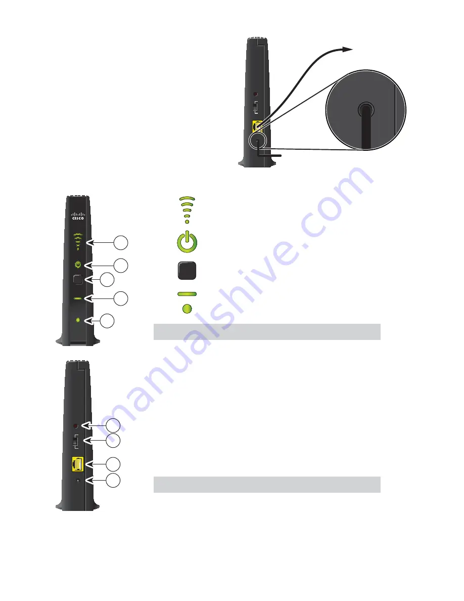
Connecting the Wireless Access Point to the Gateway
1. Connect the 12 VDC Power Supply plug on
the access point to the wall power outlet.
Use only the power adapter provided with
the product.
2. Connect the power plug to the power
receptacle on the wireless access point.
3. Connect one end of the RJ-45 Ethernet
cable to the Ethernet port on the wireless
access point.
4. Connect the other end of the RJ-45 Ethernet
cable to an available Ethernet port on your
gateway.
5. Ensure that the mode switch on the back panel is pointing to AP.
1
Wireless Signal Strength LEDs (applicable only
when the VEN501 is used as a wireless client)
2
Power
LED
3
WPS
Wi-Fi Protected Setup (WPS) button
4
Wi-Fi/Paired
LED
5
Ethernet Link LED
Note:
This illustration may vary from the actual product.
1 Reset
Restores factory default settings when held
for more than 10 seconds
2 Mode
Converts the wireless access point to a
Switch
wireless
client
3 Ethernet
Connects the wireless access point to a
Port
router/gateway or a receiver (in case the
VEN501 is used as a wireless client)
4 Power
Connects device to the external 12 VDC
power
supply
Note:
This illustration may vary from the actual product.
Pairing the Wireless Access Point and Receiver
1. Press the
OK
button on the receiver.
2. Press the
WPS
button on the wireless access point.
SIGNAL
POWER
PAIRED
LINK
VEN501
WPS
T15875
1
2
3
4
5
Reset
Ethernet
12VDC
CL
AP
T15876
1
2
3
4
T15877
Power
Receptacle
Reset
Ethernet
12VDC
CL
AP
12VDC
Gateway
Ethernet Port
RJ-45
Cable
To Wall
Power Outlet
Содержание ISB7105
Страница 1: ...Installation Manual Cisco IPTV Receivers Model ISB7105 ...
Страница 2: ...2 ...
Страница 6: ...6 ...
Страница 31: ...31 ...


