Description
Item
SIM 1 (away from device)
3
Step 5
Push in each SIM until it clicks into place. When the SIMs are installed, re-attach the access plate previously removed
with a screwdriver. Torque to 2.8 to 3.8 inch-lbs (0.9-1.1 newton meter).
Note
: Ensure the cover is properly aligned with the screw hole.
Step 6
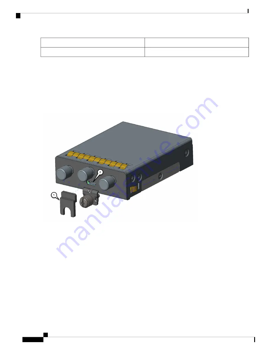
If your Pluggable Module is the type that has a USB port, make sure that the USB cover is properly installed. Place the
USB cover (
1
) with the plug indentation against the USB port (
2
). The half circle of the USB cover fits behind the latch
lock screw. See
Figure 23: USB Port Cover Installation, on page 40
for details.
Figure 23: USB Port Cover Installation
Step 7
Tighten the latch lock screw to a torque of 2.8 to 3.8 inch-lbs (0.3 to 0.4 newton meter). Refer to
Finished Installation, on page 41
for a finished USB cover installation.
IR1101 Industrial Integrated Services Router Hardware Installation Guide
40
Installing the Router
Pluggable Module
Содержание IR1101
Страница 2: ... 2018 2019 Cisco Systems Inc All rights reserved ...
Страница 6: ...IR1101 Industrial Integrated Services Router Hardware Installation Guide vi Contents ...
Страница 11: ...IR1101 Industrial Integrated Services Router Hardware Installation Guide 5 Preface Safety Warnings ...
Страница 32: ...IR1101 Industrial Integrated Services Router Hardware Installation Guide 26 Product Overview SFP Module ...


