3-7
Cisco IP/TV 3400 Series Servers User Guide
OL-4467-01
Chapter 3 Installing the IP/TV Server
Installing Cisco IP/TV 3425 and 3425A Server Units
Connecting Cables
To connect network, monitor, keyboard, and mouse cables to the Cisco IP/TV
Server, follow these steps:
Step 1
Plug the monitor cable into the onboard video port on the IP/TV Server back
panel.
Step 2
Connect the other end of the monitor cable to a monitor.
Step 3
Connect a keyboard and mouse to the keyboard port and mouse ports on the IP/TV
Server back panel.
Step 4
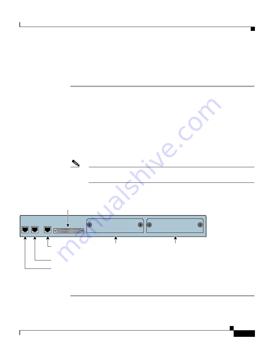
For network connections, insert a Category 5 UTP cable into the
Ethernet port labeled “Ethernet 0” on the IP/TV Server front panel. (See
Figure 3-7
.) When active, the System LED on the left front corner of the Cisco
IP/TV 3400 Series Server is lit.
Note
The console port and Ethernet port 1 are not used by Cisco IP/TV 3400
Series Servers.
Figure 3-7
Cisco IP/TV 3425 and 3425A Servers—Front Panel Connectors
Step 5
Connect the other end of the network cable to a hub or switch in your network.
55004
CONSOLE
ETHERNET 0
ETHERNET 1
SCSI LVD ONLY
SLOT 0
SLOT 1
Console
(not supported in IP/TV)
Ethernet 0
Ethernet 1
(not supported in IP/TV)
SCSI LVD only
Slot 0
Slot 1
Содержание IP/TV 3400 Series
Страница 4: ......
Страница 12: ...Cisco 90 Day Limited Hardware Warranty Terms xii Cisco IP TV 3400 Series Servers User Guide OL 4467 01 ...
Страница 21: ...xxi Cisco IP TV 3400 Series Servers User Guide OL 4467 01 Preface Command Syntax Conventions ...
Страница 112: ...Appendix B Sample Hosts File B 2 Cisco IP TV 3400 Series Servers User Guide OL 4467 01 ...
Страница 126: ...Index IN 8 Cisco IP TV 3400 Series Servers User Guide OL 4467 01 ...


