background image

22

Switch Installation

Installing the Switch

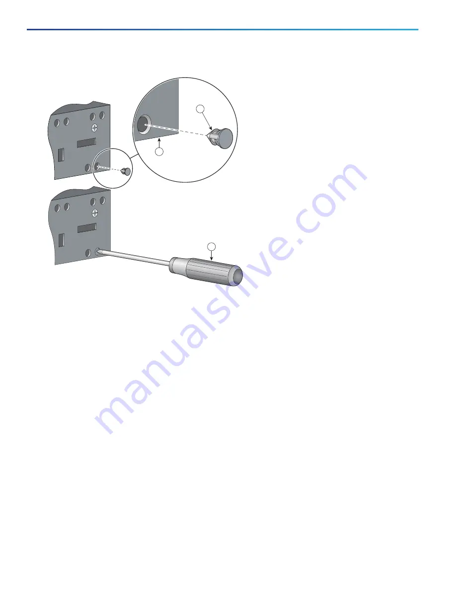
Figure 12

Inserting the Rubber Plug


1.

Identify your bracket mounting position. See 

Figure 15 on page 25

 or 

Figure 16 on page 26

2.

Insert the rubber plugs in the appropriate holes on both sides of the switch. See 

Figure 13 on page 23

 or 

Figure 14 

on page 24

3.

Use a screwdriver or pen to completely push in the rubber plugs. See 

Figure 12 on page 22

.

4.

Install the brackets on both sides of the switch. See 

Figure 15 on page 25

 or 

Figure 16 on page 26

.

1

Rubber plug

3

Screwdriver

2

Switch

255738

2

3

1

Содержание IE 3010

Страница 1: ...cause serious burns or weld the metal object to the terminals Statement 43 Warning Read the installation instructions before you connect the system to its power source Statement 1004 Warning This unit is intended for installation in restricted access areas A restricted access area can be accessed only through the use of a special tool lock and key or other means of security Statement 1017 Warning ...

Страница 2: ...e humidity around the switch does not exceed 95 percent noncondensing Altitude at the installation site is not higher than 10 000 feet For 10 100 and 10 100 1000 fixed ports cable lengths from the switch to connected devices are not more than 328 feet 100 meters For cable lengths for small form factor pluggable SFP module connections see the SFP Module Cables page 74 and the module documentation A...

Страница 3: ...nce the switch must be installed only in a rack mid mounting position If you install the switch in a front rack mounting cable side or power supply side position or in a wall mounting position a mechanical failure can occur that results in the switch becoming detached from the rack Statement 403 Attaching Brackets for 19 Inch Racks Figure 10 on page 20 and Figure 11 on page 21 show how to attach b...

Страница 4: ...ing the Switch Figure 10 Attaching Brackets for 19 Inch Racks 1 Mid mounting position 3 Cable side mounting position 2 Phillips flat head screws 4 Power supply side mounting position 208366 2 1 2 2 3 4 Ci sco IE 3010 Ci sco IE 3010 ...

Страница 5: ...ugs are not supplied with the switch You can order a kit part number IE 3010 IP30KIT containing the rubber plugs You can order a kit part number IE 3010 IP30KIT that contains the rubber plugs Figure 12 on page 22 shows a close up of the rubber plug You can install the rubber plugs in the holes as shown in Figure 13 on page 23 and Figure 14 on page 24 1 Phillips flat head screws 3 Power supply side...

Страница 6: ...26 2 Insert the rubber plugs in the appropriate holes on both sides of the switch See Figure 13 on page 23 or Figure 14 on page 24 3 Use a screwdriver or pen to completely push in the rubber plugs See Figure 12 on page 22 4 Install the brackets on both sides of the switch See Figure 15 on page 25 or Figure 16 on page 26 1 Rubber plug 3 Screwdriver 2 Switch 255738 2 3 1 ...

Страница 7: ...Switch Installation Installing the Switch Figure 13 Inserting the Rubber Plugs 1 Rubber plug 3 Cable side mounting position 2 Mid mounting position 4 Power supply side mounting position 255739 1 2 1 3 1 4 ...

Страница 8: ...24 Switch Installation Installing the Switch Figure 14 Inserting the Rubber Plugs 1 Rubber plug 3 Power supply side mounting position 2 Cable side mounting position Ci scoCGS2520 255740 1 2 1 3 ...

Страница 9: ...llation Installing the Switch Figure 15 Attaching Brackets for 19 Inch Racks 1 Mid mounting position 3 Cable side mounting position 2 Phillips flat head screws 4 Power supply side mounting position 255750 1 2 3 4 2 2 ...

Страница 10: ...ce If you use 23 inch brackets or ETSI brackets you can insert the rubber plugs in the same holes as shown in Figure 13 on page 23 or Figure 14 on page 24 before installing the brackets 1 Phillips flat head screws 3 Power supply side mounting position 2 Cable side mounting position Cisco CGS 2520 PSU2 2 255751 3 1 1 ...

Страница 11: ...ance If you use 23 inch brackets you can insert the rubber plugs in the same holes as shown in Figure 13 on page 23 or Figure 14 on page 24 before installing the brackets 1 Phillips flat head screws 3 Power supply side mounting position 2 Cable side mounting position Ci sco CGS 2520 Ci sco CGS 2520 Ci sco CGS 2520 279173 2 2 3 2 1 1 1 3 1 1 ...

Страница 12: ...in Figure 13 on page 23 or Figure 14 on page 24 before installing the brackets Rack Mounting the Switch After you attach the brackets on the switch use the four supplied number 12 Phillips machine screws to attach the brackets to the rack See Figure 19 on page 29 1 Phillips flat head screws 3 Power supply side mounting position 2 Cable side mounting position Ci sco CGS 2520 Ci sco CGS 2520 Ci sco ...

Страница 13: ...uring the LED panels on the devices in the rack Use the supplied black screw shown in Figure 19 on page 29 to attach the cable guide to the left or right bracket For configuration instructions about the CLI setup program go to Configuring the Switch with the CLI Setup Program page 81 1 Mid mounting position 4 Phillips machine screws 2 Cable screw 5 Power supply side mounting position 3 Cable side ...

Страница 14: ...tatement 378 Warning For mounting railway application equipment and for EN50155 standard compliance the switch must be installed only in a rack mid mounting position If you install the switch in a front rack mounting cable side or power supply side position or in a wall mounting position a mechanical failure can occur that results in the switch becoming detached from the rack Statement 403 If the ...

Страница 15: ...sides of the switch See Figure 21 on page 32 Note The rubber plugs are not supplied with the switch You can order a kit part number IE 3010 IP30KIT containing the rubber plugs 2 Use a screwdriver or pen to completely push in the rubber plugs See Figure 12 on page 22 3 Install the brackets on both sides of the switch See Figure 22 on page 32 1 Phillips truss head screws C i sco Sw i t ch Ser i es I...

Страница 16: ...Brackets Wall Mounting the Switch For the best support of the switch and cables ensure that the switch is attached securely to wall studs or to a firmly attached plywood mounting backboard 1 Rubber plug 2 Switch side 1 Phillips truss head screws Ci s co Sw i t ch Ser i es I E 3010 255741 1 2 Ci s co Sw i t ch Ser i es I E 3010 255752 1 ...

Страница 17: ...33 Switch Installation Installing the Switch Mount the switch with the side panel facing up Ensure that the Cisco logo is at the top of the switch See Figure 23 on page 34 and Figure 24 on page 35 ...

Страница 18: ...34 Switch Installation Installing the Switch Figure 23 Wall Mounting the Cisco IE 3010 24TC 1 User supplied screws C i sco Sw i t ch Ser i es I E 3010 208369 1 ...

Страница 19: ...d remove fiber optic and 1000BASE T SFP transceiver modules Installing SFP Modules These sections describe how to install and remove SFP modules SFP modules are inserted into SFP module slots on the front of the switch Field replaceable SFP modules provide the uplink interfaces send TX and receive RX You can use any combination of rugged SFP modules See Table 2 on page 8 for a list of supported mo...

Страница 20: ...attached because of potential damage to the cables the cable connector or the optical interfaces in the SFP module Disconnect all cables before removing or installing an SFP module Removing and installing an SFP module can shorten its useful life Do not remove and insert SFP modules more often than is absolutely necessary Installing Fiber Optic SFP Modules Warning Class 1 laser product Statement 1...

Страница 21: ...26 1000BASE T SFP Transceiver Caution To comply with GR 1089 intrabuilding lightning immunity requirements you must use grounded shielded twisted pair CAT5 cabling Note When connecting to a 1000BASE T compatible server workstation or router use four twisted pair straight through CAT5 cabling for the SFP transceiver port When connecting to a 1000BASE T compatible switch or repeater use four twisted...

Страница 22: ...device Refer to Troubleshooting page 59 for solutions to cabling problems Connecting to SFP Modules This section describes how to connect to a fiber optic or 1000BASE T SFP port To connect to an RJ 45 Gigabit Ethernet port see Connecting to a Dual Purpose Port page 43 For instructions on how to install or remove an SFP module see Connecting Devices to the Ethernet Ports page 44 Warning Class 1 las...

Страница 23: ... If necessary reconfigure and restart the switch or the target device Connecting to a 1000BASE T SFP Module To connect a CAT5 cable to a 1000BASE T SFP module Caution To prevent ESD damage follow standard board and component handling procedures 1 When connecting to servers workstations and routers insert a four twisted pair straight through cable in the RJ 45 connector When connecting to switches ...

Страница 24: ...is receive RX 3 Insert a dust plug into the optical ports of the SFP module 4 If the module has a bale clasp latch pull the bale out and down to eject it If the latch is obstructed and you cannot use your finger use a small flat blade screwdriver or other long narrow instrument 5 Grasp the SFP module and carefully remove it from the slot 6 Place the module in an antistatic bag or other protective ...

Страница 25: ...SFP Module Patch Cable To remove an SFP module patch cable from the SFP module slot release the connector and pull it from the slot Replacing the SD Flash Memory Card 1 Locate the SD flash memory card slot on the cable side of the switch 2 Use a number 1 Phillips screwdriver to loosen the captive screw See Figure 31 on page 42 208372 Ci sco IE 3010 POW ER OVER ETHERNET POW ER OVER ETHERNET POW ER ...

Страница 26: ...ive Screw 3 Pull the cover open and pull the cover tab from the hinge See Figure 32 on page 42 Figure 32 Removing the SD Slot Cover 4 Gently push the SD flash memory card to eject it See Figure 33 on page 43 Place it in an antistatic bag to protect it from static discharge 208563 208566 ...

Страница 27: ...uct Statement 1008 Caution Do not remove the rubber plugs from the SFP module port or the rubber caps from the fiber optic cable until you are ready to connect the cable The plugs and caps protect the SFP module ports and cables from contamination and ambient light Before connecting to the SFP module ensure that you understand the port and cabling stipulations in the Installation Guidelines page 1...

Страница 28: ...CAT5 CAT5e or CAT6 UTP cable The 10BASE T traffic uses Category 3 or Category 4 cable The autonegotiation feature is enabled by default on the switch At this setting the switch ports configure themselves to operate at the speed of the attached device If the device does not support autonegotiation you can set the switch port speed and duplex parameters To maximize performance either let the ports a...

Страница 29: ...ontrol whether or not a port automatically provides power to a connected IP phone or an access point To access an advanced PoE planning tool use the Cisco Power Calculator on Cisco com http tools cisco com cpc launch jsp You can use this application to calculate the power supply requirements for a specific PoE configuration The results show output current output power and heat dissipation Warning ...

Страница 30: ...k and key or other means of security Statement 1072 Caution Category 5e and Category 6 cables can store high levels of static electricity Always ground the cables to a suitable and safe earth ground before connecting them to the switch or other devices Where to Go Next You can use the default configuration or use any of the management options described in the Management Options page 16 to change t...

Отзывы: