


Maintaining and Upgrading the Router 5-3
Accessing the Router Internal Components
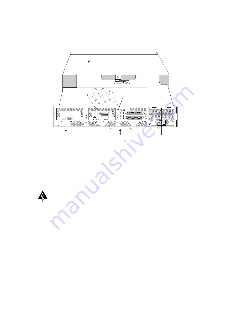
Figure 5-1
Component Tray Removal for Chassis With a Safety Latch
Step 6
While supporting the component tray with one hand, push down on the safety latch tab
while pulling out on the component tray.
Step 7
Set the component tray on your work surface.
Removing the Component Tray from a Chassis without a Safety Latch
Warning
Hazardous voltages may exist in or near the power supply, so use extreme caution when
working near the power supply. Before starting any of these procedures, turn off power to the
system, unplug the power cord, disconnect any cables at the ports, and connect your ESD-preventive
wrist strap.
Follow these steps to remove the component tray from a chassis without a safety latch.
Step 1
Turn off the system power.
Step 2
Put on your ESD-preventive wrist strap.
Step 3
Remove all network and power cables.
Step 4
Loosen the (nonremovable) screw in the back of the router chassis, labeled Chassis release
screw in Figure 5-2.
Rear of chassis
Handle
AUX
CONSOLE
INPUT 100-240VAC 50/60HZ 3.0-1.5 AMPS
Safety latch tab
Hand supporting
component tray
H1965
Chassis shell
Chassis release
screw
Содержание Explorer 4700
Страница 8: ...viii Cisco 4000 Series Hardware Installation and Maintenance For European Community Use Only F 1 ...
Страница 18: ...xviii Cisco 4000 Series Hardware Installation and Maintenance Document Conventions ...
Страница 116: ...Cable Specifications 2 Book Title 78 xxxxx xx ...
Страница 132: ...D 6 Cisco 4000 Series Hardware Installation and Maintenance Entering the ROM Monitor Program ...
Страница 134: ...E 2 Cisco 4000 Series Hardware Installation and Maintenance For United Kingdom Use Only ...
Страница 136: ...F 2 Cisco 4000 Series Hardware Installation and Maintenance For European Community Use Only ...


