background image

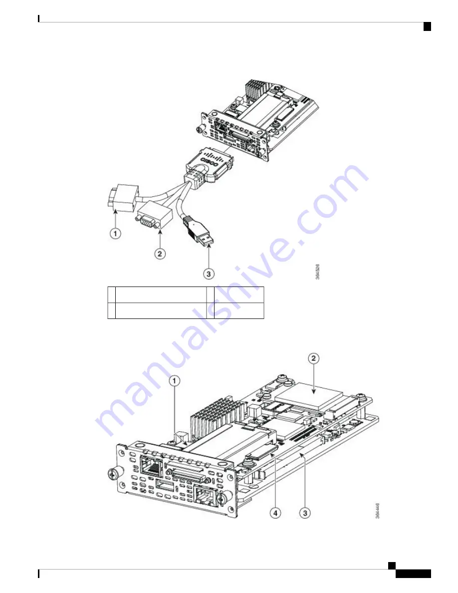
Figure 27: KVM Connector

USB connector

2

DB15 connector—video port

1

DB9 connector—serial port

3

The following figure shows the internal components of the NIM E-Series NCE.

Figure 28: Internal Components of the NIM E-Series NCE

Cisco UCS E-Series Servers and the Cisco UCS E-Series Network Compute Engine Hardware Installation Guide

55

NIM E-Series NCE—Front Panel and Components

Содержание EHWIC E Series

Страница 1: ...rver refresh Table 2 New and Changed Information for Software Release 3 1 1 Updated Sections Changed in Software Release Description Feature Hardware Requirements Hardware Information for the M3 E Series Servers Single Wide E Series Servers and the SM E Series NCE Front Panel and Components 3 1 1 Support added to install the UCS E160S M3 K9 into the Cisco ISR 4000 series Single Wide E Series Serve...

Страница 2: ...ted Sections Changed in Software Release Description Feature Hardware Information for the M2 E Series Servers 2 2 1 Support added to install the SM E Series Network Compute Engine SM E Series NCE into the Generation 2 Cisco Integrated Services Routers Cisco ISR G2 and the Cisco ISR 4451 X Integrated Services Router Cisco ISR 4451 X SM E Series Network Compute Engine Hardware Information for the M2...

Страница 3: ...ications deployed either as bare metal on operating systems such as Microsoft Windows or Linux or as virtual machines on hypervisors such as VMware vSphere Hypervisor Microsoft Hyper V or Citrix XenServer The E Series Servers are purpose built with powerful Intel Xeon processors for general purpose compute They come in the following form factors single wide and double wide The single wide E Series...

Страница 4: ...ries Server 6 cores CPU with PCIe 1 8 GHz clock speed The following M2 E Series Servers and SM E Series NCE are supported UCS EN120S M2 SM E Series NCE 2 cores CPU 2 0 GHz clock speed UCS E140S M2 Single wide E Series Server 4 cores CPU 1 8 GHz clock speed UCS E160D M2 Double wide E Series Server 6 cores CPU 2 0 GHz clock speed UCS E180D M2 Double wide E Series Server 8 cores CPU 1 8 GHz clock spe...

Страница 5: ...SATA SAS SSD SED and External USB SATA SAS SSD SED and External USB SATA SAS SSD SED and External USB Storage Type SAS 10K RPM SATA 7200 RPM and SAS SSD Drives 1 Supports 2 Drives SAS 10K RPM SATA 7200 RPM and SAS SSD Drives 1 Supports 3 Drives SAS 10K RPM SATA 7200 RPM and SAS SSD Drives1 Supports 2 Drives HDD 200 GB to 2 TB 200 GB to 3 TB 200 GB to 2 TB Storage Capacity2 2 Gigabit Ethernet Inter...

Страница 6: ...351 1 E Series Server ISR 4431 None ISR 4451 X 1 E Series Server 2911 ISR G2 1 E Series Server 2921 ISR G2 1 E Series Server 2951 ISR G2 2 E Series Servers 3925 ISR G2 3 E Series Servers 3925e ISR G2 3 E Series Servers 3945 ISR G2 4 E Series Servers 3945e ISR G2 4 E Series Servers ISR 4321 None ISR 4331 1 E Series Server ISR 4351 2 E Series Servers ISR 4431 None ISR 4451 X 2 E Series Servers Maxim...

Страница 7: ... SAS SSD Drives 1 Supports 3 Drives SAS 10K RPM SATA 7200 RPM and SAS SSD Drives3 Supports 2 Drives SAS 10K RPM SATA 7200 RPM Supports 2 Drives HDD 200 GB to 3 TB 200 GB to 2 TB 500 GB to 2 TB Storage Capacity4 2 Gigabit Ethernet Interfaces 2 Gigabit Ethernet Interfaces 2 Gigabit Ethernet Interfaces Internal Network Interface 2 USB Connectors 2 RJ 45 Gigabit Ethernet Connectors 1 Management Port 1...

Страница 8: ...nstalled with the same type of storage device either all SAS drives or all SATA drives 4 The size of the HDD and SSD drives is expressed in decimal form For instance GB 1 billion bytes not 2 30 bytes TB 1 trillion bytes not 2 40 bytes Hardware Information for the M3 E Series Servers Cisco UCS E Series M3 servers have a dedicated SSD flash disk based on eMMC technology This eMMC storage is not a us...

Страница 9: ... Network Interface 2 USB connector 2 RJ 45 10 Gigabit Ethernett Interfaces TE2 and TE3 1 KVM port supports VGA 1 USB 1 serial DB9 1 Management Port TE2 and TE3 interfaces support only GE switch 10GBps interfaces can connect only to devices with 1GBps speeds or higher Note 2 USB connector 2 RJ 45 10 Gigabit Ethernett Interfaces TE2 and TE3 1 KVM port supports VGA 1 USB 1 serial DB9 1 Management Por...

Страница 10: ...s Internal Network Interface 1 Standard USB Connector 1 Mini USB Connector 1 RJ 45 Gigabit Ethernet Connector 1 Console Port External Interfaces 1921 1941 2901 2911 2921 2951 3925 3925e 3945 3945e Router Platforms 1921 ISR G2 1 NCE 1941 ISR G2 1 NCE 2901 ISR G2 2 NCEs 2911 ISR G2 2 NCEs 2921 ISR G2 2 NCEs 2951 ISR G2 2 NCEs 3925 ISR G2 2 NCEs 3925e ISR G2 1 NCE 3945 ISR G2 2 NCEs 3945e ISR G2 1 NC...

Страница 11: ...r 1 Management Port 1 KVM Port Supports VGA 1 USB 1 Serial DB9 External Interfaces 4321 4331 4351 4431 4451 X Router Platforms ISR 4321 2 NCEs ISR 4331 2 NCEs ISR 4351 3 NCEs ISR 4431 3 NCEs ISR 4451 X 3 NCEs Maximum Number of NCEs per Router Supported Cisco EtherSwitch EHWIC and Cisco EtherSwitch Service Modules The following table shows the Cisco EtherSwitch Enhanced High Speed WAN Interface Car...

Страница 12: ...r cable active SFP H10GB ACU7M SFP 10GBASE CU 10 meter cable active SFP H10GB ACU10M SFP Optical JDSU PLRXPL SC S43 22 N SFP SFP 10GBase SR Optical SFP 10G SR Recommended Safety Practices This section describes recommended practices for safe and effective installation of the hardware and includes the following topics Safety Recommendations To prevent hazardous conditions follow these safety recomm...

Страница 13: ...sult in complete or intermittent equipment failure Always observe the following electrostatic discharge damage ESD prevention procedures when installing removing and replacing the E Series Servers or the NCEs Make sure that the router chassis is electrically connected to earth ground Wear an ESD preventive wrist strap and make sure that it makes good contact with your skin Connect the wrist strap ...

Страница 14: ...rnings are available in the Cisco Network Modules and Interface Cards Regulatory Compliance and Safety Information document at http www cisco com en US docs routers access interfaces rcsi IOHrcsi html IMPORTANT SAFETY INSTRUCTIONSThis warning symbol means danger You are in a situation that could cause bodily injury Before you work on any equipment be aware of the hazards involved with electrical c...

Страница 15: ...anger Do not use this product near water for example near a bath tub wash bowl kitchen sink or laundry tub in a wet basement or near a swimming pool Statement 1035 Danger Never install telephone jacks in wet locations unless the jack is specifically designed for wet locations Statement 1036 Danger Never touch uninsulated telephone wires or terminals unless the telephone line has been disconnected ...

Страница 16: ...d WAN ports contain TNV circuits Both LAN and WAN ports may use RJ 45 connectors Use caution when connecting cables Statement 1021 Danger Hazardous network voltages are present in WAN ports regardless of whether power to the router is OFF or ON To avoid electric shock use caution when working near WAN ports When detaching cables detach the end away from the router first Statement 1026 Danger Befor...

Страница 17: ... single wide SM E Series NCE Figure 1 Front Panel of the Single Wide E Series Server and the SM E Series NCE Management port 2 Gigabit Ethernet port 1 LEDs for HDD1 4 Power switch 3 Hard disk drive 1 6 Keyboard Video Mouse KVM port Refer Figure 3 KVM Connector on page 18 5 USB 8 LEDs for HDD0 7 Reset switch 10 Hard disk drive 2 9 The following figure shows the front panel of the single wide E Seri...

Страница 18: ...ws the KVM connector Figure 3 KVM Connector DB15 connector video port 2 USB connector 1 DB9 connector serial port 3 The following figure shows the internal components of the single wide E Series Server Cisco UCS E Series Servers and the Cisco UCS E Series Network Compute Engine Hardware Installation Guide 18 Single Wide E Series Servers and the SM E Series NCE Front Panel and Components ...

Страница 19: ...ute Engine Integrated Management Controller Caution 3 CMOS battery located under the hard drive tray 5 Single Wide E Series Server and the SM E Series NCE LEDs The following table lists the single wide E Series Server and the SM E Series NCE LEDs and describes the LED colors and states Table 15 Single Wide E Series Server and SM E Series NCE LEDs State Color LED Status of the hard drive activity S...

Страница 20: ...ault is detected on the processor Amber Status can be one of the following Steady CIMC and CPU are both operating normally Blinking CPU is operating normally and CIMC is booting up Green Power Status can be one of the following Steady CIMC is operating normally and the CPU is powered down Blinking CIMC is in the process of booting up and the CPU is powered down Amber Left LED shows the speed of th...

Страница 21: ... Intel server Note Do not swap SD cards between UCS E Series Servers See the Recovering from a Faulty SD Card section in the CLI Configuration Guide for the Cisco UCS E Series Servers and the Cisco UCS E Series Network Compute Engine Integrated Management Controller Caution 6 Serial port 5 Management port 8 Gigabit Ethernet ports GE2 and GE3 7 Optional HDD2 PCIe assembly or blank slot 10 USB ports...

Страница 22: ...itch This resets all CMOS settings Note 2 Power switch 1 Console port 4 LEDs 3 USB port 0 Each port provides up to 500 mA of current Devices that require higher power such as CD DVD ROM need their own external power 6 Management Port 5 Hard disk drives HDD3 and HDD2 8 Gigabit Ethernet ports TE2 and TE3 7 USB port 1 Each port provides up to 500 mA of current Devices that require higher power such a...

Страница 23: ...le Wide E Series Server LEDs The following table lists the double wide E Series Server LEDs and describes the LED colors and states Table 16 Double Wide E Series Server LEDs State Color LED No memory is installed in this socket Off M0 6 Memory M0 is installed Green Memory M0 is installed but fault is detected Amber Cisco UCS E Series Servers and the Cisco UCS E Series Network Compute Engine Hardwa...

Страница 24: ... drive activity Steady Hard drive is present Blinking Active Off Inactive or there is no power supplied to the CPU Green D1A Fault is detected on the hard drive Amber D1F If an optional hard drive is present the status of the hard drive activity can be one of the following Steady Hard drive is present Blinking Active Off Inactive or there is no power supplied to the CPU If there is a PCIe card ins...

Страница 25: ...ols and equipment Step 3 Removing the Blank Faceplate from the Router s SM Slot on page 26 Remove the blank faceplates from the SM slots that you want to use Step 4 Preparing the Router s SM Slot for E Series Server or SM E Series NCE Installation on page 26 Depending on the type of server that you want to install either remove or install the slot divider Step 5 Installing the E Series Server or t...

Страница 26: ...e blank faceplates for future use What to do next What to Do Next Prepare the router slot for E Series Server or SM E Series NCE installation See the Preparing the Router s SM Slot for E Series Server or SM E Series NCE Installation Preparing the Router s SM Slot for E Series Server or SM E Series NCE Installation Several Cisco routers have flexible SM slots to support various Cisco server modules...

Страница 27: ...ace a double wide E Series Server with a single wide E Series Server or SM E Series NCE you must install a slot divider Use this procedure to install a slot divider for a single wide E Series Server or a SM E Series NCE Before You Begin Make sure that you connect the wrist strap clip to an unpainted portion of the chassis frame to channel unwanted ESD voltages to ground Procedure Procedure Step 1 ...

Страница 28: ...Series Server or SM E Series NCE into the router See the Installing the E Series Server or the SM E Series NCE into the Router Removing the Slot Divider for Double Wide E Series Server Installation To install a double wide E Series Server in the SM slot you must remove the slot divider Use this procedure to remove the slot dividers from the SM slot Before You Begin Make sure that you connect the w...

Страница 29: ...extra low voltage SELV circuits to telephone network voltage TNV circuits LAN ports contain SELV circuits and WAN ports contain TNV circuits Some LAN and WAN ports both use RJ 45 connectors Use caution when connecting cables Statement 1021 Danger Hazardous network voltages are present in WAN ports regardless of whether power to the unit is OFF or ON To avoid electric shock use caution when working...

Страница 30: ...nd one or two single wide servers in the other slots then you must use a second AC and PoE supply to support this configuration Procedure Procedure Step 1 Turn off the electrical power to the router Leave the power cable plugged in to the channel ESD voltages to ground Alternatively the Cisco 3900 ISR G2 and the Cisco ISR 4000 series support OIR See the Online Insertion and Removal E Series Server...

Страница 31: ...Do Next 1 Load a compatible Cisco IOS image See the Cisco ISR G2 E Series Server NCE and Cisco IOS Software Release Compatibility section in the Release Notes for Cisco UCS E Series Servers and the Cisco UCS E Series Network Compute Engine Release 3 x 2 Connect the E Series Server or SM E Series NCE to the network and then power up the router and the server 3 Install blank faceplates to cover any ...

Страница 32: ...at the blank faceplate is flush with the chassis Verifying E Series Server or SM E Series NCE Installation Before You Begin 1 Install the E Series Server or SM E Series NCE into the router 2 Load a compatible Cisco IOS image 3 Power on the server Procedure To verify the E Series Server or SM E Series NCE installation use one of the following commands To display a high level overview of the entire ...

Страница 33: ... upgrade information see the Upgrading Firmware chapter in the Getting Started Guide for Cisco UCS E Series Server Modules and the Cisco UCS E Series Network Compute Engine Integrated Management Controller on Cisco com If you migrate the E Series Server into the Cisco ISR 4000 series without first updating the CIMC firmware the E Series Server might continuously reset To stop the reset and install...

Страница 34: ... the server activates the currently inactive image Server cimc firmware activate 1 2 Step 7 Exits the CIMC session Click Ctrl a Ctrl q Step 8 Enables error recovery Router hw module subslotslot subslotmaintenance disable Step 9 Enter the commands in Step 9 and Step 10 from the router Note Reloads the E Series Server Router hw modulesubslotslot subslot reload Step 10 This reload power cycles the E ...

Страница 35: ...lease 15 2 4 M to 15 4 2 T or ucse subslot slot port adapter shutdown command is applicable from Cisco IOS Release 15 4 3 M Example ucse subslot slot port adapter shutdown Before proceeding with the next command verify that the E Series Server has shut down When the E Series Server shuts down the power LED turns orange You can also use CIMC to verify if the E Series Server has powered down Note Ex...

Страница 36: ...Cisco ISR 4000 Series Procedure Purpose Command or Action Enables privileged EXEC mode enable Step 1 Example Enter your password if prompted Router enable Shuts down the E Series Server gracefully ucse subslot slot 0 shutdown Step 2 Example Before proceeding with the next command verify that the E Series Server has shut down When the E Series Server shuts down the power LED turns orange You can al...

Страница 37: ... rovides complete data redundancy if one disk fails RAID 5 disk striping with distributed parity Data and parity information is striped and distributed across all disks in the array with distributed parity information RAID 5 requires three hard disks and provides limited fault tolerance The double wide E Series Servers support adding a hot spare drive under RAID 1 If one of the disk drives under R...

Страница 38: ... wrist strap clip to an unpainted portion of the chassis frame to channel unwanted ESD voltages to ground Procedure Use this procedure to install or replace a hard disk drive on the E Series Servers The procedure to install or replace the Hard Disk drives on an E Series Server is the same for M1 M2 and M3 servers Note Procedure Step 1 Turn off power to the router Alternatively the Cisco 3900 ISR G...

Страница 39: ...ssembly 2 Hard disk drive 1 Captive screws on hard disk drive assembly 4 Cover faceplate 3 Step 3 Optional If the slot is empty use the screwdriver to loosen the screws on the bracket and then remove the bracket see the following figure Cisco UCS E Series Servers and the Cisco UCS E Series Network Compute Engine Hardware Installation Guide 39 Installing or Replacing Hard Disk Drives on the E Serie...

Страница 40: ...the carrier to avoid rattling during operation Step 8 Replace the faceplate Step 9 Restart the E Series Server Step 10 Configure the new HDD as the new hotspare disk drive For the configuration procedure see the GUI Configuration Guide for UCS E Series Servers and the Cisco UCS E Series Network Compute Engine Integrated Management Controller Installing and Replacing the Memory DIMMS in the E Serie...

Страница 41: ...ower supply connection All connections must be removed to de energize the unit Statement 1028 Danger Blank faceplates and cover panels serve three important functions they prevent exposure to hazardous voltages and currents inside the chassis they contain electromagnetic interference EMI that might disrupt other equipment and they direct the flow of cooling air through the chassis Do not operate t...

Страница 42: ...ure shows the location of the memory DIMMs in a double wide E Series Server The double wide E Series Servers support up to 48 GB of DDR3 memory DIMMs Note Cisco UCS E Series Servers and the Cisco UCS E Series Network Compute Engine Hardware Installation Guide 42 Memory DIMM Location ...

Страница 43: ...rver The following figure shows the location of the memory DIMMs in the double wide E Series Servers UCS E180D M3 and UCS E1120D M3 Cisco UCS E Series Servers and the Cisco UCS E Series Network Compute Engine Hardware Installation Guide 43 Memory DIMM Location ...

Страница 44: ...and the Cisco ISR 4000 series support OIR See the Online Insertion and Removal E Series Servers on page 34 Note Step 2 Locate the DIMM on the E Series Server See the Memory DIMM Location on page 41 Step 3 Pull the latches away from the DIMM at both ends to lift the DIMM slightly Take care not to dislodge the battery that is adjacent to the DIMM connectors Caution Step 4 Pull the DIMM out of the so...

Страница 45: ...following memory configuration Mix DIMM sizes and densities within a channel Partially populate a channel Unevenly populate the DIMMs between CPUs DIMMs must be installed in the following order in the double wide E Series Servers 1 DIMM 1 center DIMM 2 DIMM 2 closest to the CPU 3 DIMM 0 outboard DIMM DIMMs must be installed in the following order in the single wide E Series Servers 1 DIMM 0 closes...

Страница 46: ...tep 3 Make sure that both latches on the DIMM connector are in the open position Step 4 Orient the DIMM so that the polarization notch on the DIMM lines up with the notch on the connector Figure 20 Polarization Notch on the DIMM Polarization notch 1 Step 5 Insert the DIMM into the connector Step 6 Carefully and firmly press the DIMM into the connector until the latches close onto the DIMM Make sur...

Страница 47: ...Front Panel and Components Figure 22 Front Panel of the EHWIC E Series NCE LED for the system 2 LED for power 1 VGA port 4 Console port 3 Gigabit Ethernet port GE2 5 Figure 23 Internal Components of the EHWIC E Series NCE Cisco UCS E Series Servers and the Cisco UCS E Series Network Compute Engine Hardware Installation Guide 47 EHWIC E Series NCE ...

Страница 48: ...he CPU is powered down Amber Steady Operation is normal Note If DRAM is not detected the SYS LED still displays solid green Note Blinking System is booting before entering the EFI shell Green SYS Fault is detected on the processor Amber Left LED shows the condition of the traffic Blinking Traffic is detected Off There is no traffic Green GE Port LEDs Right LED shows whether the link is established...

Страница 49: ...n unpainted portion of the chassis frame to channel unwanted ESD voltages to ground Procedure Procedure Step 1 Using either a number 1 Phillips screwdriver or a small flat blade screwdriver unscrew the captive screws and remove the blank faceplate from the chassis slot you plan to use See Figure 24 and 25 A blank interface faceplate with double thumb screws 1 Step 2 Save the blank faceplates for f...

Страница 50: ...4 Cisco ISR G2 EHWIC Slot Divider Retention screws 1 Step 3 Pull the slot divider straight out of the EHWIC slot What to do next What to Do Next Install the EHWIC E Series NCE into the router See the Installing the EHWIC E Series NCE into the Router on page 50 Installing the EHWIC E Series NCE into the Router The EHWIC E Series NCE can be installed either before or after mounting the router whiche...

Страница 51: ... future use 3 Removed the slot divider from the EHWIC slot for EHWIC E Series NCE installation See the Removing Slot Dividers from EHWIC Slots on page 49 4 Connected a wrist strap clip to an unpainted portion of the chassis frame to channel unwanted ESD voltages to ground Procedure Procedure Step 1 Turn off electrical power to the router Leave the power cable plugged in to channel ESD voltages to ...

Страница 52: ...chassis rear panel Do not connect cables to EHWIC E Series NCE until you have installed it Caution Step 5 Using a number 1 Phillips or flat blade screwdriver tighten the captive mounting screws on the EHWIC E Series NCE faceplate What to do next What to Do Next 1 Load a compatible Cisco IOS image 2 Connect the EHWIC E Series NCE to the network and then power up the router and the NCE 3 Verify that...

Страница 53: ...Enhanced WAN Interface Card UCS Server on Slot 0 SubSlot 3 DESCR Enhanced WAN Interface Card UCS Server PID UCS EN120E M2 K9 VID V01 SN FOC17462K2A NAME C3900 AC Power Supply 1 DESCR C3900 AC Power Supply 1 PID PWR 3900 AC VID V03 SN SNI1511C8SM Online Insertion and Removal EHWIC E Series NCE OIR is not supported on the EHWIC E Series NCE Note Installing the Field Programmable Gate Array Image in ...

Страница 54: ...ctions for more information about NIM E Series NCE NIM E Series NCE Front Panel and Components The following figure shows the front panel of the NIM E Series NCE Figure 26 Front Panel of the NIM E Series NCE Management port 2 EN LED 1 USB 4 Power LED 3 KVM port used for keyboard video and mouse KVM connector Refer Figure 27 KVM Connector on page 55 6 LED for the system 5 LED for the SSD drive 8 GE...

Страница 55: ...l port 3 The following figure shows the internal components of the NIM E Series NCE Figure 28 Internal Components of the NIM E Series NCE Cisco UCS E Series Servers and the Cisco UCS E Series Network Compute Engine Hardware Installation Guide 55 NIM E Series NCE Front Panel and Components ...

Страница 56: ... is powered down Amber Steady Operation is normal Note If DRAM is not detected the SYS LED still displays solid green Note Blinking System is booting before entering the EFI shell Green SYS Fault is detected on the processor Amber Blinks when the CIMC is operating normally Green IMC Blinks when the SSD is operating normally Green SSD Left LED shows the condition of the traffic Blinking Traffic is ...

Страница 57: ...V circuits and WAN ports contain TNV circuits Some LAN and WAN ports both use RJ 45 connectors Use caution when connecting cables Statement 1021 Danger Hazardous network voltages are present in WAN ports regardless of whether power to the unit is OFF or ON To avoid electric shock use caution when working near WAN ports When detaching cables detach the end away from the unit first Statement 1026 Da...

Страница 58: ...NCE 1 Do not touch the NIM E Series NCE board Handle the NIM E Series NCE by the edges of the faceplate to reduce the risk of damage to the card Caution Step 4 Using the faceplate push the NIM E Series NCE into place until you feel the NIM seat securely into the connector on the router backplane The NIM faceplate should contact the chassis rear panel Do not connect cables to NIM E Series NCE until...

Страница 59: ...f the entire physical system use the show platform command Router show platform Chassis type ISR4351 K9 0 1 UCS EN140N M2 K9 ok 3w5d 1 0 UCS E140DP M1 K9 ok 4w6d 2 ISR4351 K9 ok 5w2d R0 ISR4351 K9 ok active 5w2d F0 ISR4351 K9 ok active 5w2d P0 PWR 4450 AC ok 5w2d P2 ACS 4450 FANASSY ok 5w2d Slot CPLD Version Firmware Version 0 14080523 15 4 3r S1 1 14080523 15 4 3r S1 2 14080523 15 4 3r S1 R0 1408...

Страница 60: ...ing the NIM E Series NCE in a Cisco ISR 4000 Series A Cisco ISR 4000 series that is up and running can detect when an NIM E Series NCE is inserted in the NIM slot After the router detects the NIM E Series NCE the router software enables power to the server Removing the COA The procedure to remove the COA is the same for M1 M2 and M3 servers Note In the event that you need to return the E Series Se...

Страница 61: ...and the Cisco UCS E Series Network Compute Engine Related Documentation For more information about Cisco UCS E Series Servers and the Cisco UCS E Series Network Compute Engine see the following related documentation For links to the following http www cisco com en US docs unified_computing ucs e 1 0 roadmap e_ series_road_map html Cisco UCS E Series Servers and the Cisco UCS Network Compute Engine...

Страница 62: ...ogrammer s Guide for Cisco UCS E Series Servers and the Cisco UCS E Series Network Compute Engine Troubleshooting Guide for Cisco UCS E Series Servers and the Cisco UCS E Series Network Compute Engine Open Source Used in Cisco UCS E Series Servers Documentation Guides for Third Party Plug in Tools For information about installing and connecting the Cisco 2900 series and Cisco 3900 ISRs see the Cis...

Отзывы: