


3-16
Cisco CVA122/CVA122E Hardware Installation Guide
OL-0799-02 (05/2001)
Chapter 3
Installing the Cisco CVA122/CVA122E Cable Voice Adapter
Power-On and Initialization Sequence
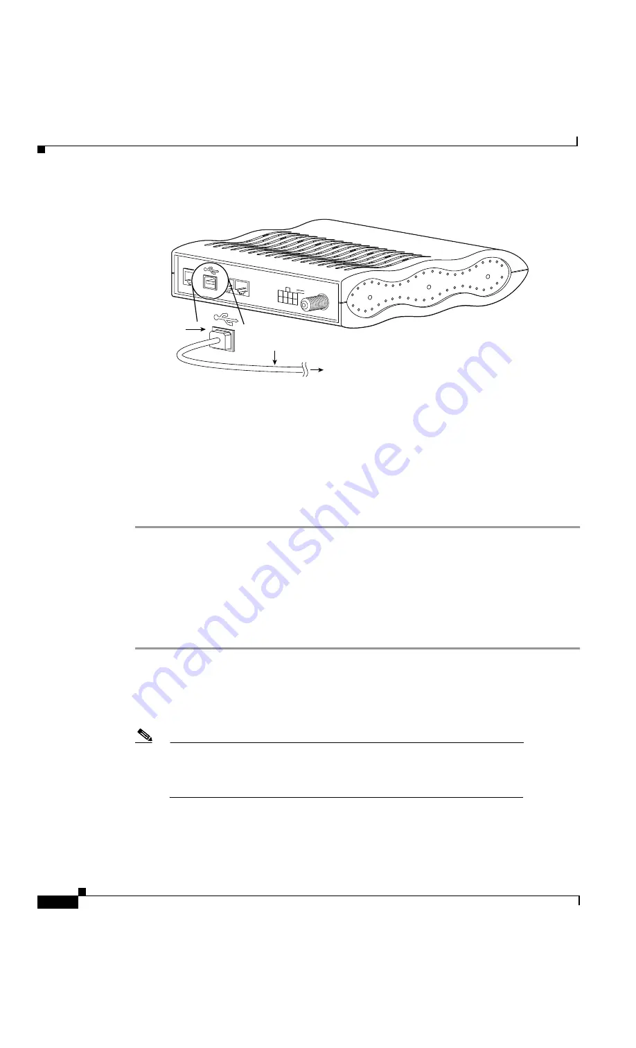
Figure 3-9
Connecting the USB Cable to the Cisco CVA122/CVA122E Cable Voice Adapter
Step 5
Verify that the USB LED on the front panel of the Cisco CVA122/CVA122E Cable Voice Adapter turns
on. If this LED does not light, check that each connector on the USB cable is fully inserted into the USB
port on the computer (or the hub) and the USB port on the cable voice adapter. If using a hub, try
disconnecting it from the computer and connecting the Cisco CVA122/CVA122E Cable Voice Adapter
directly to the computer; if the USB LED then turns on, check that the USB hub is properly installed
and powered.
Step 6
Install the required USB driver software—the Windows software will detect the installation of a new
USB device and automatically begin the software installation procedure. For information on installing
the software device drivers required for USB connectivity, see the instructions that accompany the USB
driver software CD that is shipped with the cable voice adapter.
Power-On and Initialization Sequence
When the Cisco CVA122/CVA122E Cable Voice Adapter is connected and powered on, it executes
automatic self-diagnostic and installation procedures. The following procedure describes what you
should see during this process.
Step 1
Watch the LEDs on the front of the Cisco CVA122/CVA122E Cable Voice Adapter. When the unit first
powers on, the LEDs briefly light and then turn off. As self-test is executed, various LEDs light to reveal
the progress of the unit’s self-tests.
Step 2
The Message LED then blinks as the cable voice adapter completes its self-tests and boots a Cisco IOS
image.
Note
The LEDs on the front panel display the power-on self-test progress and status.
Should the self-test fail, these LEDs display error codes. See the “Initialization
and Self-Test Problems” section on page 4-2 for a description of self-test LED
error patterns.
Step 3
During the cable voice adapter’s initialization and download, the Message LED blinks. After
completing the download procedure (which could take up to 10 minutes if downloading a new
Cisco IOS image as well as a configuration file), the Message LED turns off and the Cable Status LED
turns on solid.
35997
To computer
USB Type B
Receptacle
USB Type A-B
Cable
V1+V2
X
USB
USB
Phone
Power
+5,-30,-56
V
Cable TV In
Ethernet
V2


