


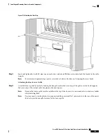


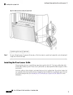


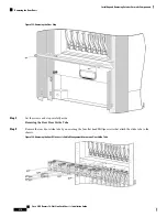


You may need to use the plastic tie wraps to attach the power shelf AC power cables to the rear of the power
shelves to provide enough clearance for the louver grille.
Note
Figure 118: Attaching the Rear Louver Grille
Step 2
Press the louver grille firmly against the brackets until its ball studs snap onto the support bracket's ball stud retainers.
What to do next
You may now power up the chassis. The chassis is ready for use.
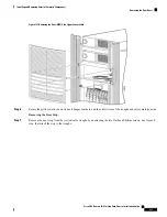
Removing the Default Rear (MSC) Cosmetic Components
This section describes how to remove the default cosmetic components, shown in
Side Exterior Cosmetic Components—Fixed Configuration Shown
, from the rear (MSC) side of the LCC.
This section includes the following procedures:
• Removing the Upper Air Grille and Vertical Brackets
• Removing the Rear Kick Panel
Cisco CRS Routers 16-Slot Line Card Chassis Installation Guide
206
Installing and Removing Exterior Cosmetic Components
Removing the Default Rear (MSC) Cosmetic Components
Содержание CRS-16-LCC/M
Страница 20: ...Cisco CRS Routers 16 Slot Line Card Chassis Installation Guide xx Preface Preface ...
Страница 118: ...Cisco CRS Routers 16 Slot Line Card Chassis Installation Guide 98 Installing and Removing Power Components Steps ...
Страница 252: ...Cisco CRS Routers 16 Slot Line Card Chassis Installation Guide 232 Upgrading Chassis Components Steps ...


