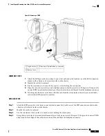


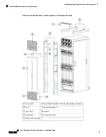


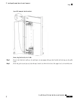
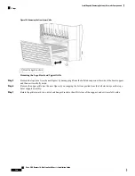

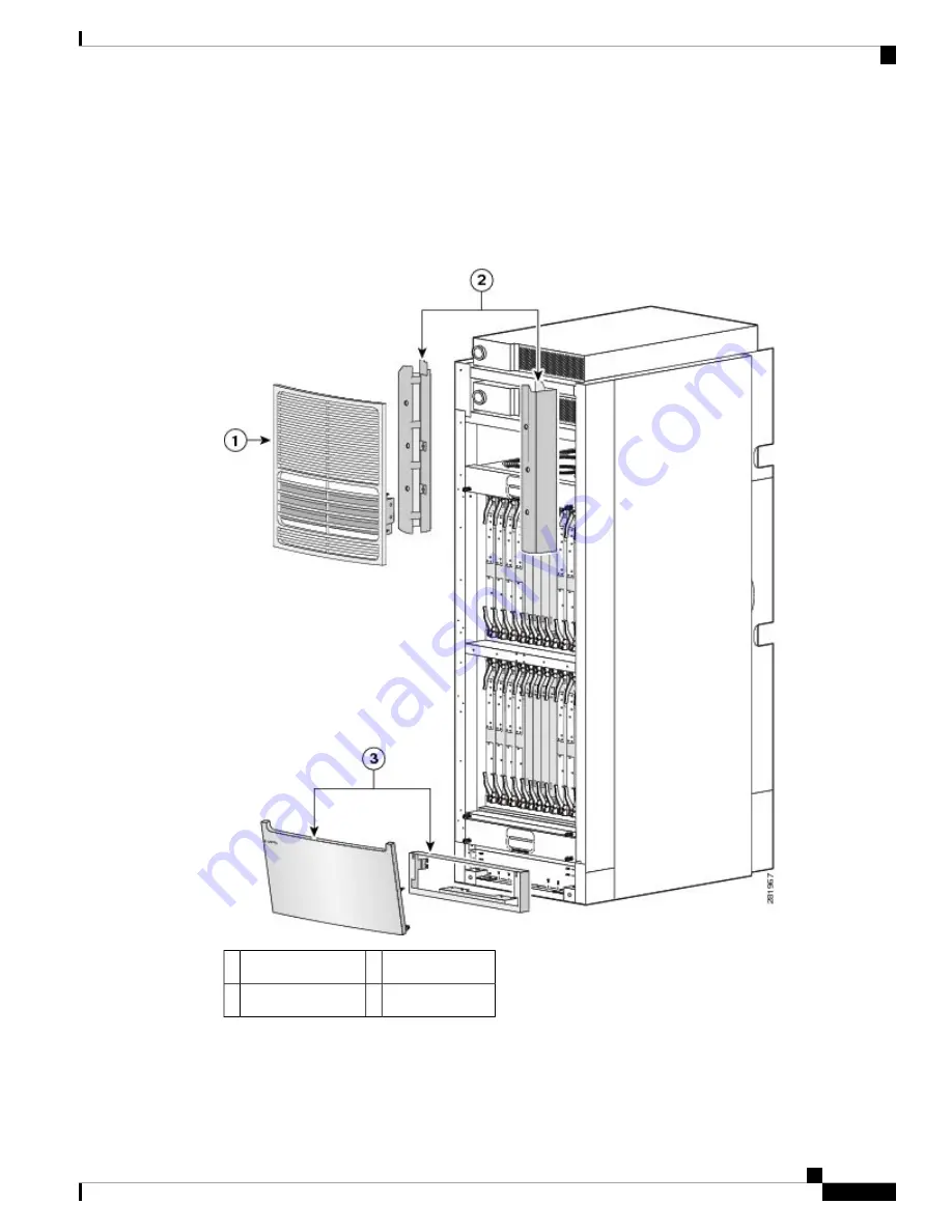
This figure shows the exterior cosmetics on the rear (MSC) side of a LCC, with fixed configuration power
shelves installed. The upper air grille and vertical brackets are shipped with the LCC, but are not pre-installed
on the system the system. The rear kick panel kit, shown in the figure, is not included as part of the default
shipment and is available to be ordered seperately (Cisco product number CRS-16-LCC-BCK-KP). The rear
view of a LCC with modular configuration power shelves installed is similar.
Figure 93: Rear (MSC) Side Exterior Cosmetic Components—Fixed Configuration Shown
Vertical brackets
2
Upper air grille
1
Rear kick panel kit
3
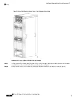
The following figure shows the exterior cosmetics for the rear (MSC) side of an optional multi chassis system
with fixed configuration power shelves installed. The rear view of an optional multi chassis system with
modular configuration power shelves installed is similar.
Cisco CRS Routers 16-Slot Line Card Chassis Installation Guide
173
Installing and Removing Exterior Cosmetic Components
Information About Exterior Cosmetic Components
Содержание CRS-16-LCC/M
Страница 20: ...Cisco CRS Routers 16 Slot Line Card Chassis Installation Guide xx Preface Preface ...
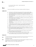
Страница 118: ...Cisco CRS Routers 16 Slot Line Card Chassis Installation Guide 98 Installing and Removing Power Components Steps ...
Страница 252: ...Cisco CRS Routers 16 Slot Line Card Chassis Installation Guide 232 Upgrading Chassis Components Steps ...


