background image


3-9

Cisco Content Delivery Engine Hardware Installation Guide

OL-13478-01

Chapter 3      Installing the Software and Initially Configuring a CDE

Running the BIOS Setup Utility

Running the BIOS Setup Utility for the CDE-200

Perform the following steps to run the BIOS setup utility for the CDE-200:

Step 1

Ensure that the CDE-200 is powered off.

Step 2

Attach the USB CD-ROM drive to any available USB port at the rear of the CDE-200 (see 

Figure 3-1

).

Step 3

Power on the USB CD-ROM drive.

Step 4

Power on the CDE-200 and wait for the initial BIOS screen to appear.

Note

Step 5

 through 

Step 12

 are required only for the initial installation. The BIOS setup does not need to be 

changed for the second and subsequent installations or recovery.

Step 5

To enter the BIOS Setup menu, press 

Delete

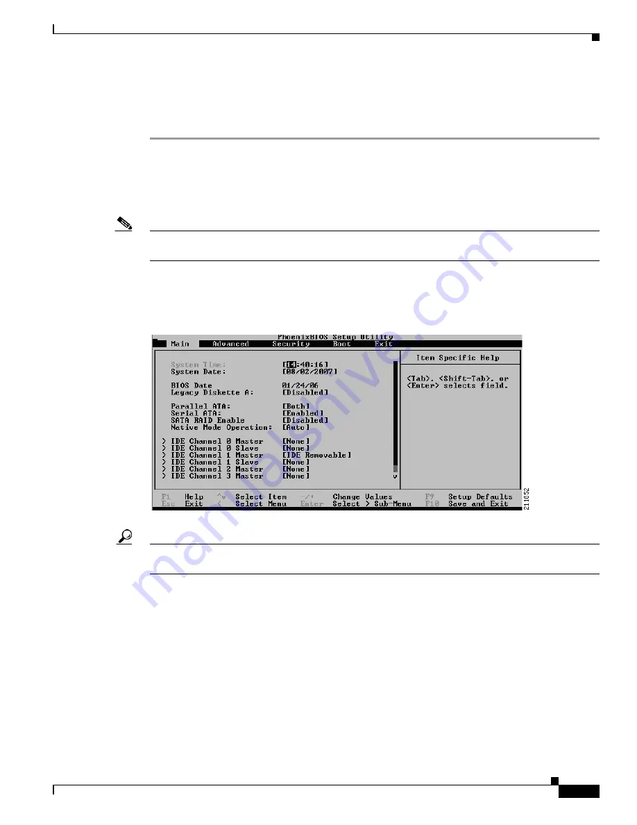
 as instructed at the bottom of the BIOS screen. The Main 

menu appears (see 

Figure 3-13

).

Figure 3-13

Main Menu

Tip

Ctrl-Backspace 

functions the same as the 

Delete

 key if you are viewing the initial BIOS screen through 

a remote terminal server.

Step 6

Use the arrow keys to navigate to the Advanced menu and press 

Enter

. The Advanced menu appears (see 

Figure 3-14

).

Содержание Content Delivery Engine CDE100

Страница 1: ... Installation Guide August 2007 THE SPECIFICATIONS AND INFORMATION REGARDING THE PRODUCTS IN THIS MANUAL ARE SUBJECT TO CHANGE WITHOUT NOTICE ALL STATEMENTS INFORMATION AND RECOMMENDATIONS IN THIS MANUAL ARE BELIEVED TO BE ACCURATE BUT ARE PRESENTED WITHOUT WARRANTY OF ANY KIND EXPRESS OR IMPLIED USERS MUST TAKE FULL RESPONSIBILITY FOR THEIR APPLICATION OF ANY PRODUCTS Text Part Number OL 13478 01...

Страница 2: ...e the equipment to one side or the other of the television or radio Move the equipment farther away from the television or radio Plug the equipment into an outlet that is on a different circuit from the television or radio That is make certain the equipment and the television or radio are on circuits controlled by different circuit breakers or fuses Modifications to this product not authorized by ...

Страница 3: ... H A P T E R 2 Installing the CDEs 2 1 Server Types 2 1 Safety Warnings 2 1 Tools and Parts Required 2 4 Installing the CDEs 2 4 Rack Installation Safety Guidelines 2 4 Preparing the CDEs for Rack Installation 2 4 Installing in the Rack 2 5 Making Physical Connections 2 6 Connecting Power Cords 2 6 Connecting Network Cables 2 8 Installing or Removing Disk Drives 2 8 C H A P T E R 3 Installing the ...

Страница 4: ...E R 4 Hardware Troubleshooting 4 1 Troubleshooting Ethernet Adapters 4 1 Troubleshooting SATA Drives 4 2 A P P E N D I X A Technical Specifications A 1 CDE 100 A 1 CDE 200 A 2 Management A 2 A P P E N D I X B Connector Pin Assignments B 1 CDE Server Connectors B 1 Serial Console Interface Connector Pin Assignments B 2 Serial Port Connector B 3 Ethernet Connector Pin Assignments B 3 Ethernet Port C...

Страница 5: ...al changes to this document Document Organization Document Version Date Change Summary OL 13478 01 August 20 2007 This is the first version of this document Chapter Description Chapter 1 Overview of Content Delivery Engines Provides a brief introduction to the Content Delivery Engines CDEs Chapter 2 Installing the CDEs Provides the necessary information to properly install the CDS hardware compone...

Страница 6: ...lable from the Cisco com site Release Notes for the Cisco Internet Streamer CDS 2 0 Release Notes for Cisco CDA Visual Quality Experience Application Release 2 0 Cisco Internet Streamer CDS 2 0 Software Configuration Guide Cisco Content Delivery Engine 110 Hardware Installation Guide Cisco CDA Visual Quality Experience Application User Guide Release 2 0 Cisco Internet Streamer CDS 2 0 Documentatio...

Страница 7: ...nformation on obtaining documentation obtaining support providing documentation feedback security guidelines and also recommended aliases and general Cisco documents see the monthly What s New in Cisco Product Documentation which also lists all new and revised Cisco technical documentation at http www cisco com en US docs general whatsnew whatsnew html ...

Страница 8: ...viii Cisco Content Delivery Engine Hardware Installation Guide OL 13478 01 Preface ...

Страница 9: ... features The Cisco Internet Streamer Content Delivery System CDS release 2 0 CDEs are the CDE 100 and CDE 200 servers Figure 1 1 shows the front view of the CDE 100 and Figure 1 2 shows the rear view of the CDE 100 Figure 1 1 CDE 100 Front View Figure 1 2 CDE 100 Rear View Figure 1 3 shows the front view of the CDE 200 and Figure 1 4 shows the rear view of the CDE 200 Figure 1 3 CDE 200 Front Vie...

Страница 10: ... and six Gigabit Ethernet ports Each CDE is designed to be rack mounted in a standard 19 inch rack with a depth of 30 inches Front Panel Control Buttons Figure 1 5 shows the CDE 100 front panel and describes the front panel control buttons Figure 1 5 CDE 100 Front Panel Control Buttons Figure 1 6 shows the CDE 200 front panel and describes the front panel control buttons 1 Power Powers up the devi...

Страница 11: ... the button 2 Reset Resets the device and runs the power on self test POST You may need to use a pen or the end of a straightened paper clip to press the button Note This is a hardware reset button and does not restore the device to the factory default software settings 211767 1 2 1 2 No LED Color State Description 1 Power Blue On Power is flowing to the device 2 Hard disk drive activity Blue On A...

Страница 12: ...nnectors The CDEs support the following I O connectors on the rear of the device Ethernet connectors Serial connector Video and audio connectors on optional adapter Figure 1 9 shows the location of the CDE 100 back panel ports and connectors No LED Color State Description 1 Power Blue On Device is powering on 2 Hard disk drive activity Blue On Associated hard disk drive is in use 3 Ethernet port 1...

Страница 13: ... Personal System 2 PS 2 or Universal Serial Bus USB However the keyboard and mouse are supported by the BIOS for POST and the BIOS Setup Utility as described in Chapter 3 Installing the Software and Initially Configuring a CDE 1 Power connector 5 VGA interface 2 Mouse connector 6 GigabitEthernet 1 0 3 Keyboard connector 7 GigabitEthernet 2 0 4 Serial console interface 211770 4 5 6 7 1 2 3 1 Power ...

Страница 14: ...reaming interface NICs are installed in slots 4 and 5 counting from the left most slot In this hardware configuration the Gigabit Ethernet interfaces on the motherboard are detected as interfaces 3 0 and 4 0 and the interfaces on the NICs are detected as 1 0 2 0 5 0 and 6 0 The interface numbering must be taken into consideration when configuring IP addresses and port channels ...

Страница 15: ...gh capacity hard drives There are three distinct server types in the Content Delivery System System Manager CDSM CDE 100 or CDE 200 Service Engine SE CDE 200 Service Router SR CDE 200 Depending on your application you may have multiple SEs and SRs A network switch is employed to link multiple servers together within a larger network Safety Warnings These warnings are translated into several langua...

Страница 16: ... of security and is controlled by the authority responsible for the location Statement 37 Warning Before working on equipment that is connected to power lines remove jewelry including rings necklaces and watches Metal objects will heat up when connected to power and ground and can cause serious burns or weld the metal object to the terminals Statement 43 Warning Only trained and qualified personne...

Страница 17: ...ply connection All connections must be removed to de energize the unit Statement 1028 Warning Ultimate disposal of this product should be handled according to all national laws and regulations Statement 1040 Warning This product requires short circuit overcurrent protection to be provided as part of the building installation Install only in accordance with national and local wiring regulations Sta...

Страница 18: ...view the following guidelines Two or more people are required to install the device in a rack Ensure that the room air temperature is below 95 F 35 C Do not block any air vents usually 6 inches 15 cm of space provides proper airflow Plan the device installation starting from the bottom of the rack Install the heaviest device in the bottom of the rack Do not extend more than one device out of the r...

Страница 19: ...r The one in the upright position is the secondary IDE connector If necessary swap the internal CD ROM drive with the CompactFlash drive in order to ensure the CompactFlash drive is connected to the secondary IDE cable CDE 200 Make sure the 80 GB hard drive is connected to the primary IDE cable and the CompactFlash drive is connected to the secondary IDE cable If necessary swap the internal CD ROM...

Страница 20: ... is not achieved because of uneven mechanical loading Making Physical Connections After mounting the servers continue the hardware setup by making the physical connections for power and network Caution The unit is intended for indoor use It is provided with numerous standard USB and Ethernet ports This product is not intended to be directly connected to the Telecommunication Network System Additio...

Страница 21: ...hernet interfaces on the motherboard are detected as interfaces 3 0 and 4 0 and the interfaces on the NICs are detected as 1 0 2 0 5 0 and 6 0 The interface numbering must be taken into consideration when configuring IP addresses and port channels 1 Power connector 5 VGA interface 2 Mouse connector 6 GigabitEthernet 1 0 3 Keyboard connector 7 GigabitEthernet 2 0 4 Serial console interface 211770 4...

Страница 22: ...hard drive from the chassis The hard drives on the CDE 100 are monitored using Self Monitoring Analysis and Reporting Technology S M A R T and statistics are displayed through the Administrative Interface as well as sent to the CDSM For more information about S M A R T see the Cisco Internet Streamer CDS 2 0 Software Configuration Guide The CDE 100 contains four disk drives see Figure 2 3 and the ...

Страница 23: ... CDE 200 Front Cover Step 3 Unlock the latch by pressing the safety lock button on the front of the latch see Figure 2 6 Step 4 Unlatch the disk drive tray from the locking clip and swing open the main latch see Figure 2 6 Step 5 Carefully pull the disk drive out of its drive tray slot Step 6 Insert a new disk drive into the drive tray slot and make sure it is properly seated Step 7 Close the latc...

Страница 24: ...2 10 Cisco Content Delivery Engine Hardware Installation Guide OL 13478 01 Chapter 2 Installing the CDEs Installing the CDEs ...

Страница 25: ...ring a CDE page 3 14 Verifying the CDSM page 3 15 Before You Begin You need the following to perform the initial installation and configuration of the CDS CDE USB CD ROM drive for CDE 200 only provided Internal IDE compact flash drive pre installed Terminal server connection with the following parameters 9600 baud 8 bits No parity Redirection After BIOS POST is off in CDE BIOS setup Console redire...

Страница 26: ...h1 g2 0 The four interface ports on the stream interfaces are GigabitEthernet 3 0 GigabitEthernet 4 0 GigabitEthernet 5 0 and GigabitEthernet 6 0 using channel bonding 2 see number 8 in Figure 3 1 eth2 g3 0 eth3 g4 0 eth4 g5 0 eth5 g6 0 Figure 3 1 Interface Port Locations Caution In some CDE 200 chassis the streaming interface NICs are installed in slots 4 and 5 counting from the left most slot In...

Страница 27: ... pins 2 and 3 connected instead of 1 and 2 Pin 1 is closest to the rear of the case and pin 3 is closest to the front Running the BIOS Setup Utility Running the BIOS setup utility is different for the CDE 100 and the CDE 200 therefore this section provides a separate BIOS setup procedure for each CDE Running the BIOS Setup Utility for the CDE 100 Perform the following steps to run the BIOS setup u...

Страница 28: ... Backspace functions the same as the Delete key if you are viewing the initial BIOS screen through a remote terminal server Step 5 From the Main menu choose Boot and press Enter The Boot Settings menu appears see Figure 3 4 Figure 3 4 Boot Settings Menu Step 6 From the Boot Settings Menu choose Boot Settings Configuration and press Enter The Boot Settings Configuration screen appears see Figure 3 ...

Страница 29: ...rn to the Boot menu and choose Boot Device Priority The Boot Device Priority screen appears see Figure 3 6 Figure 3 6 Boot Device Priority Screen Step 8 Use the on screen instructions to move the elements into the following order 1 CD ROM drive first boot device 2 Flash device first hard drive 3 Removable devices 4 Network device Caution The devices must be in the correct order for the installatio...

Страница 30: ...0 Press Esc to return to the Main menu Use the arrow keys to choose Advanced and press Enter The Advanced Settings menu appears see Figure 3 8 Figure 3 8 Advanced Settings Menu Step 11 Choose IDE Configuration and press Enter The IDE Configuration screen appears see Figure 3 9 Figure 3 9 IDE Configuration Screen a Set the IDE Configuration option to P ATA Only b Set the S ATA Running Enhanced Mode...

Страница 31: ...re Super I O Chipset screen appears see Figure 3 10 Figure 3 10 Configure Super I O Chipset Screen Set the Serial Port2 Address option to Disabled Step 13 Press Esc to return to the Advanced menu Choose Remote Access Configuration and press Enter The Configure Remote Access Type and Parameters screen appears see Figure 3 11 Figure 3 11 Configure Remote Access Type and Parameters screen a Set the S...

Страница 32: ... is displayed at the conclusion of this boot sequence Welcome to the installer The installer enables installation of a new software image onto your system or recovers a previous image in the event that the hardware was changed MODEL CDE100 FLASH found directory validated COOKIE valid IMAGE DEVELOPMENT jbohach lnx02 data jbohach ws ipvideo refact dev 1 FLASHDEV dev hdX Installer Main Menu 1 Configu...

Страница 33: ...CD ROM drive Step 4 Power on the CDE 200 and wait for the initial BIOS screen to appear Note Step 5 through Step 12 are required only for the initial installation The BIOS setup does not need to be changed for the second and subsequent installations or recovery Step 5 To enter the BIOS Setup menu press Delete as instructed at the bottom of the BIOS screen The Main menu appears see Figure 3 13 Figu...

Страница 34: ...gure 3 14 Advanced Menu Step 7 Choose Boot Features and press Enter The Boot Features screen appears see Figure 3 15 Figure 3 15 Boot Features Screen a Set the QuickBoot Mode option to Enabled b Set the Quiet Boot option to Disabled c Set the After Power Failure option to Power On Step 8 Use the Down arrow key to expand Hard Drive and expose its subelements see Figure 3 16 ...

Страница 35: ...ce 2 Flash device first hard drive 3 Removable devices 4 Network device Caution The devices must be in the correct order for the installation to be successful Step 10 Press Esc to return to the Main menu To configure IDE set the IDE Channel 0 Master option to None and the IDE Channel 1 Master option to 128 this is compact flash card see Figure 3 17 Figure 3 17 Main Menu Note On the CDE 200 the Pri...

Страница 36: ... after POST option to On Step 12 When you are finished navigate to the Exit submenu and choose Exit Saving Changes Press Yes when prompted see Figure 3 19 Figure 3 19 Exit Saving Changes Screen Step 13 Ensure that the CD with the CDS software image is in the USB CD drive and press Enter to confirm and reboot the system Your configuration is saved you exit the BIOS Setup menu and the system reboots...

Страница 37: ...EL CDE200 FLASH found directory validated COOKIE valid IMAGE DEVELOPMENT jbohach lnx02 data jbohach ws ipvideo refact dev 1 FLASHDEV dev hdX Installer Main Menu 1 Configure Network 2 Manufacture flash 3 Install flash cookie 4 Install flash image from network 5 Install flash image from cdrom 6 Install flash image from disk 7 Wipe out disks and install bin image 8 Exit and reboot 9 Force manufacturi...

Страница 38: ...ts from the IDE CF drive with the data installed from the CD All previous data is removed and the original system remains unaffected Caution Be sure to disconnect the CD ROM drive before rebooting the system or it will not boot with the normal image Initially Configuring a CDE This section provides the steps to perform the initial software configuration after a CDE has been loaded with a CDS softw...

Страница 39: ... the default gateway 10 0 0 0 Please enter the domain name server ip 172 16 0 0 Please enter the domain name spcdn com Please enter the hostname CDStr1 Please enter CDSM Content Delivery System Manager IP or Host name 209 165 201 0 Press any key to continue CDE configure terminal CDE cms enable This initiates database services on the device that you just configured Note Once the IP default gateway...

Страница 40: ...he Software and Initially Configuring a CDE Verifying the CDSM Figure 3 20 CDSM Login Page The CDSM Main menu appears see Figure 3 21 Figure 3 21 Main Menu Step 3 From the CDSM Main menu choose the Devices tab A list of all your registered Service Engines and Service Routers appears see Figure 3 22 ...

Страница 41: ...rk are listed Step 5 If a device is not listed restart the CMS for that device by using either the console or Telnet connection and entering the following commands from the global configuration mode CDE config no cms enable CDE config cms enable The installation is now complete Refer to the Cisco Internet Streamer CDS 2 0 Software Configuration Guide for information on configuring and using the CD...

Страница 42: ...3 18 Cisco Content Delivery Engine Hardware Installation Guide OL 13478 01 Chapter 3 Installing the Software and Initially Configuring a CDE Verifying the CDSM ...

Страница 43: ...the LED is on for each switch port that is connected to an adapter Do not be alarmed if LED is not lit on a adapter when power is applied to the system LED illumination at system startup is dependent on the version of the adapter All configured adapters should have LED illumination once the Cisco Content Delivery Service has been started Step 5 Verify that the port configuration on the switch Most...

Страница 44: ... SATA drives for a total of 24 SATA drives The SATA controller card is located in slots 1 5 and 6 counting from the right as you are facing the rear of the chassis see Figure 1 4 on page 1 2 If the system reports that there is a problem with the SATA drives such as the drives not being recognized or being reported as bad use the following procedure Step 1 Reboot the system Step 2 Reseat the drive ...

Страница 45: ...Capacity Four 3 5 SCSI 73GB hard drives Interface 2 Gigabit Ethernet interfaces Memory 4 Gigabytes RAM Processor 64bit Dual Core Intel Xeon 3 60 GHz 800FSB 2MB Cache Operating System Linux kernel 2 6 10 contained on the Compact Flash device Operating System Disk Four 3 5 SCSI 73GB hard drives Cable length Maximum length of 330 ft 100 m using Category 5E or higher Power 350 W peak 110 and 220 VAC F...

Страница 46: ...ernel 2 6 10 contained on the Compact Flash device Operating System Disk Two 60 Gigabit small form factor SATA hard drives Cable length Twisted Pair Maximum of 330 ft 100 m using Category 5E or higher 4 pair 902 ft 275 m maximum 62 5 125 mm Power 500 W 110 and 220 VAC or 48 VDC redundant Fan Assembly Redundant with operation alarm monitored by system Operating Temperature 32 to 122 F 0 to 50 C Hum...

Страница 47: ...s page B 2 Ethernet Connector Pin Assignments page B 3 Cable Pin Assignments page B 5 CDE Server Connectors Figure B 1 shows the location of all the CDE 100 connectors servers and Figure B 2 shows the location of all connectors for a CDE 200 server Figure B 1 CDE 100 Connector Locations Caution Do not install cables for any not used ports 1 Power connector 5 VGA interface 2 Mouse connector 6 Gigab...

Страница 48: ... Interface Connector Pin Assignments The serial console interface connector is a 9 pin RS 232 D type DTE connector A null modem cable is required to connect a workstation running the Linux or Windows operating system Table B 1 lists the pin assignments for the serial console interface connector 1 Power connectors 5 VGA interface 2 Mouse connector 6 GigabitEthernet 1 0 3 Keyboard connector 7 Gigabi...

Страница 49: ...n Assignments The Ethernet connector is an 8 pin modular RJ 45 connector Table B 2 through Table B 4 list the Ethernet connector pin assignments 1 5 6 9 83193 Table B 2 Ethernet Connector Pin Assignments for T568A RJ 45 Pin Wire Color T568A Wire Diagram T568A 10BASE T 100BASE T 1000BASE T Signal 1 White Green Transmit BI_DA 2 Green Transmit BI_DA 3 White Orange Receive BI_DB 4 Blue Unused BI_DC 5 ...

Страница 50: ...d pair UTP cable to the RJ 45 connector on the back of the device Note The 100BASE TX 1000BASE TX Ethernet standard requires that the cabling in the network be Category 5 or higher Figure 2 4 shows the pin number assignments for the Ethernet RJ 45 port 4 Blue Unused BI_DC 5 White Blue Unused BI_DC 6 Green Receive BI_DB 7 White Brown Unused BI_DD 8 Brown Unused BI_DD Table B 4 RJ 45 Crossover Cable...

Страница 51: ...gure B 5 Figure B 6 and Figure B 7 show the pin assignments for the cable connection for an RS 232 null modem RJ45 straight through and RJ 45 crossover cable respectively Figure B 5 Pin Assignments for RS 232 Null Modem 1 8 Link LED green Activity LED green 83195 RXD TXD GND DB 9 Female End view 5 1 9 6 DB 9 Female 1 2 3 4 5 6 7 8 9 1 2 3 4 5 6 7 8 9 TO HOST COMPUTER 211777 End view 5 1 9 6 ...

Страница 52: ... Assignments and Wiring for an RJ 45 Straight Through Cable Figure B 7 Pin Assignments and Wiring for an RJ 45 Crossover Cable 211778 1 2 3 4 5 6 7 8 1 2 3 4 5 6 7 8 Brown White Brown White Blue White Green White Orange Orange Blue Green 211779 1 2 3 4 5 6 7 8 1 2 3 4 5 6 7 8 Brown White Brown White Blue White Green White Orange Orange Blue Green ...

Страница 53: ...view 1 1 registering with CDSM 3 14 server types 2 1 CDE 100 BIOS Setup 3 3 connectors 1 5 control buttons 1 2 disk drives 2 8 hardware features 1 2 LEDs 1 3 overview 1 1 safety warnings 2 1 specifications A 1 CDE 200 BIOS Setup 3 9 configuring ports 3 2 connectors 1 5 control buttons 1 3 disk drives 2 8 hardware features 1 2 LEDs 1 4 overview 1 1 safety warnings 2 1 specifications A 2 CDS image C...

Страница 54: ...ee CDSM control buttons CDE 100 1 2 CDE 200 1 3 CD eject 1 2 power 1 2 1 3 reset 1 2 1 3 D devices verifying with the CDSM 3 17 disk drives CDE 100 2 8 CDE 200 2 8 IDE compact flash 3 1 3 13 installing 2 8 location 2 8 removing 2 8 USB CD ROM 3 1 E environment 2 6 Ethernet connector pin assignments B 3 controller B 4 port connector B 4 Ethernet adapter troubleshooting 4 1 Ethernet connector 1 4 Et...

Страница 55: ... 2 6 rack 2 5 rack safety guidelines 2 4 software installation order 3 3 tools and parts 2 4 interfaces stream 3 2 L LEDs CDE 100 1 3 CDE 200 1 4 CD ROM drive 1 3 Ethernet port 1 1 3 1 4 Ethernet port 2 1 3 1 4 hard disk drive 1 3 1 4 power 1 3 1 4 reset 1 3 M management specifications A 2 N network cables 2 8 P physical connections network cables 2 8 power cords 2 6 pin assignments B 1 10BASE T c...

Страница 56: ... SE 2 1 serial connector 1 4 Serial console interface B 2 serial ports connector pinout B 3 description B 3 server types CDSM 2 1 SE 2 1 SR 2 1 Service Engine see SE Service Router see SR specifications CDE 100 A 1 CDE 200 A 2 management A 2 technical A 1 SR 2 1 stream interfaces 3 2 T technical specifications see specifications terminal server parameters 3 1 troubleshooting Cisco Technical Assist...

Отзывы: