background image

The RJ-45 console port uses an 8-pin RJ-45 connector. The supplied RJ-45-to-DB-9 adapter cable is used to
connect the console port of the switch to a console PC. You must provide a RJ-45-to-DB-25 female DTE
adapter if you want to connect the switch console port to a terminal. You can order a kit (part number
ACS-DSBUASYN=) containing that adapter.

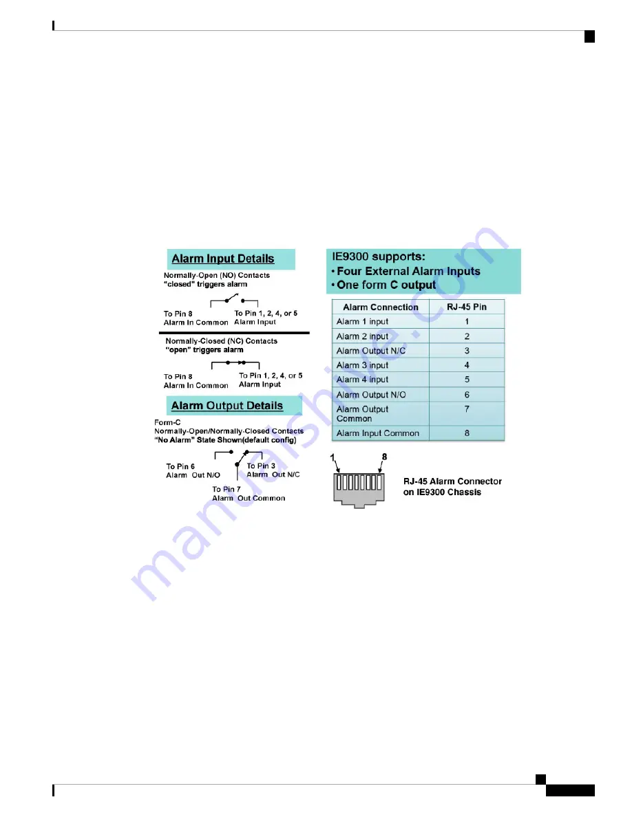
Alarm Port

The alarm port uses an RJ-45 connector.

Figure 38: Alarm Port Details

See the sections

Alarms, on page 8

and Alarm Ratings for more information.

Cables and Adapters

SFP Module Cables

Each port must match the wave-length specifications on each end of the cable, and for reliable communications,
the cable must not exceed the allowable length

For more information about SFP/SFP+ modules and cables, see

Transceiver Modules

on Cisco.com.

Cisco Catalyst IE9300 Rugged Series Switch Hardware Installation Guide

71

Cables and Connectors

Alarm Port

Содержание Catalyst IE-9310-26S2C-A

Страница 1: ...ch Hardware Installation Guide First Published 2022 04 26 Last Modified 2022 10 03 Americas Headquarters Cisco Systems Inc 170 West Tasman Drive San Jose CA 95134 1706 USA http www cisco com Tel 408 526 4000 800 553 NETS 6387 Fax 408 527 0883 ...

Страница 2: ...rights reserved Copyright 1981 Regents of the University of California NOTWITHSTANDING ANY OTHER WARRANTY HEREIN ALL DOCUMENT FILES AND SOFTWARE OF THESE SUPPLIERS ARE PROVIDED AS IS WITH ALL FAULTS CISCO AND THE ABOVE NAMED SUPPLIERS DISCLAIM ALL WARRANTIES EXPRESSED OR IMPLIED INCLUDING WITHOUT LIMITATION THOSE OF MERCHANTABILITY FITNESS FOR A PARTICULAR PURPOSE AND NONINFRINGEMENT OR ARISING FR...

Страница 3: ...e right pane of every online document Bias Free Language The documentation set for this product strives to use bias free language For purposes of this documentation set bias free is defined as language that does not imply discrimination based on age disability gender racial identity ethnic identity sexual orientation socioeconomic status and intersectionality Exceptions may be present in the docum...

Страница 4: ......

Страница 5: ...gged Series Switch 1 Switch Models 1 Front Panel 3 Display Mode Button 4 Express Setup Button 4 System LED 5 Power Supplies 5 Gigabit Ethernet Ports 7 Alarms 8 Console Ports 9 SD Card Connector 10 USB Host Port 11 Stacking Interface 11 Switch Installation 13 C H A P T E R 2 Preparing for Installation 13 Warnings 13 Installation Guidelines 15 Required Tools and Equipment 15 Cisco Catalyst IE9300 Ru...

Страница 6: ...0 Install Fiber Optic SFP Modules 31 Install 100 1000BASE T SFP Modules 31 Guidance for Connecting to SFP Modules 33 Connect to a Fiber Optic SFP Module 33 Connect to a 1000BASE T SFP Module 34 Remove SFP Modules 34 Replace the SD Flash Memory Card 35 Connecting Devices to the Ethernet Ports 35 Power Supply Installation 37 C H A P T E R 3 Power Supply Installation 37 Power Supply Modules 37 Power ...

Страница 7: ...57 Complete the Setup Program 57 Troubleshooting 63 C H A P T E R 6 Diagnosing Problems 63 Switch Boot Fast 63 Switch LEDs 63 Switch Connections 64 Bad or Damaged Cable 64 Ethernet and Fiber Optic Cables 64 Link Status 64 10 100 1000 Port Connections 65 SFP Module 65 Interface Settings 65 Ping End Device 65 Spanning Tree Loops 65 Switch Performance 66 Speed Duplex and Autonegotiation 66 Autonegoti...

Страница 8: ...rdous Location Installation Information 73 C H A P T E R 8 Hazardous Area Installation Warnings 73 North American Hazardous Location Approval 75 EMC Environmental Conditions for Products Installed in the European Union 76 Hazardous Locations Standards 76 Technical Specifications 79 C H A P T E R 9 Switch Specifications 79 Power Supply Module Specifications 81 Alarm Ratings 81 Cisco Catalyst IE9300...

Страница 9: ...tility substations intelligent transportation systems ITSs rail transportation and other similar deployments The switch fulfills the need for a high density SFP rack or wall mount switch that can function as a software defined SD Access fabric edge It provides end to end architectural uniformity in the Cisco Digital Network Architecture DNA for Internet of Things IoT for connected communities and ...

Страница 10: ... Network Essentials license For information about differences between the licenses see the Cisco Catalyst IE9300 Rugged Series Switchdata sheet on Cisco com Note All Cisco Catalyst IE9300 Rugged Series Switch models have 4 GB of DRAM four alarm inputs and one alarm output Other I O include the following SD cards socket Power input RJ 45 RS 232 console Micro USB console USB A host port For more inf...

Страница 11: ... are not associated with a specific interface are on the left side of the front panel The front panels of IE9310 and IE9320 models are nearly identical Later sections note the few differences The power supply LEDs are visible on the rear of the switch where the units are installed Note Figure 1 Cisco Catalyst IE9300 Rugged Series Switch Front Panel Alarms 6 Display mode button 1 RJ 45 console port...

Страница 12: ...edundancy modes and LEDs The IE9320 switch also has a Stack LED The modes apply to SFP and copper ports Combination ports have two port LEDs one by the SFP connector and the second by the RJ 45 connector Only one can be active at a time For details about the display modes and corresponding port LEDs see the section Gigabit Ethernet Ports on page 7 in this document Note Express Setup Button Express...

Страница 13: ...port to connect the management station Disconnect a device from a switch port and then press the Express Setup button Red System LED The system LED provides basic status about the health of the Cisco Catalyst IE9300 Rugged Series Switch Table 4 System LED System Status Color System is not powered on Off Power on self test POST is in progress Blinking green System is operating normally Green System...

Страница 14: ...s working properly The LEDs are driven directly by the power supplies and are not under software control Control by the power supplies ensures that the LEDs turn on when the power is available and remain on regardless of the software state For details about the power supply and its LED see the section Power Supply Modules on page 37 Cisco Catalyst IE9300 Rugged Series Switch Hardware Installation ...

Страница 15: ...its individual port However you can use the display mode button to cycle through the different LED modes which determines the kind of information that is shown by the port LEDs When you choose a mode the mode LED lights up solid green and the port LEDs light up as described in the following table After 5 seconds the mode LED turns off its default state Table 5 Ethernet Port LEDs Status LED Color P...

Страница 16: ...co Catalyst IE9300 Rugged Series Switch has four alarm inputs and one output You can connect up to four alarm inputs from different devices such as a door or temperature gauge to the alarm port You can use the CLI to set the alarm severity to minor or major The switch software monitors switch conditions for each port or the switch overall If the conditions present on the switch or a port do not ma...

Страница 17: ... Red Major alarm condition is present Blinking red Console Ports The Cisco Catalyst IE9300 Rugged Series Switch has two console ports one RS 232 port with an RJ 45 connector and one USB port with a micro USB connector The USB port is behind a small door on the front panel Output from the switch is always sent to both ports but input is accepted only from one port at a time The USB console LED show...

Страница 18: ... a secure digital SD card connector You can use the connector for the Swap Drive feature and to copy files on and off the system The slot is behind a door on the front panel The following table shows the SD card connector states and what they mean Table 10 SD Card LED Status Color SD card is not present Off SD card is present and working Green SD card transfer is in progress Blinking green Unsuppo...

Страница 19: ...us of active and standby maagers Table 12 Stacking interface LEDs Status Color Switch is a stack member not the active or standby stack manager Off Switch is the active stack manager or not part of a stack standalone operation Green Switch is the standby stack manager Slow blinking green An error occurred during stack manager election or another type of stack error occurred Amber Each of the two s...

Страница 20: ...Cisco Catalyst IE9300 Rugged Series Switch Hardware Installation Guide 12 Cisco IE9300 Rugged Series Overview Stacking Interface ...

Страница 21: ...the Regulatory Compliance and Safety Information for Cisco Catalyst IE9300 Rugged Series Switch They apply to all the switch models Before working on equipment that is connected to power lines remove jewelry including rings necklaces and watches Metal objects will heat up when connected to power and ground and can cause serious burns or weld the metal object to the terminals Statement 43 Warning R...

Страница 22: ...otection 10 100 1000 Ethernet Statement 1044 Warning To prevent the system from overheating do not operate it in an area that exceeds the maximum recommended ambient temperature of 140 F 60 C Statement 1047 Operating temperatures exceeding 60 C are not covered by the product safety certifications and approvals However the switch can function in the installations under the environmental conditions ...

Страница 23: ... 75 in 4 4 cm at the top bottom and sides If the switch is installed in a closed or multirack assembly the temperature around it might be greater than normal room temperature Ensure that the internal temperature does not exceed the maximum ambient temperature specifications for the switch Note Required Tools and Equipment Obtain the necessary tools and equipment Phillips screwdriver Verifying the ...

Страница 24: ... page 21 Rack Mount the Switch on page 22 To prevent bodily injury when mounting or servicing this unit in a rack you must take special precautions to ensure that the system remains stable Observe the following guidelines to ensure your safety Mount the unit at the bottom of the rack if it is the only unit in the rack When mounting this unit in a partially filled rack load the rack from the bottom...

Страница 25: ...t mid or rear mounting of the switch in the rack Step 2 Attach the brackets to the switches following the steps in the appropriate illustrations Figure 5 Attaching Brackets Front Mounting Figure 6 Attaching Brackets Midmounting Cisco Catalyst IE9300 Rugged Series Switch Hardware Installation Guide 17 Switch Installation Attach Brackets for 19 Inch Racks ...

Страница 26: ...ing the mounting brackets install the rubber plugs in the unused mounting holes The following figure shows a close up of the rubber plugs and how to install the rubber plugs in the holes Figure 8 Inserting a Rubber Plug Screwdriver 3 Rubber plug 1 Cisco Catalyst IE9300 Rugged Series Switch Hardware Installation Guide 18 Switch Installation Attach Brackets for 19 Inch Racks for IP 30 Compliance Opt...

Страница 27: ...e holes on the switch that you will not use for mounting The following illustration shows the location of holes on the switch Figure 9 Switch Hole Locations Rubber plug 1 Step 4 Insert the rubber plugs in the appropriate holes on both sides of the switch as shown in the first illustration in this section Step 5 Use a screwdriver or pen to push in the rubber plugs completely What to do next Complet...

Страница 28: ... holes as described in the section Attach Brackets for 19 Inch Racks for IP 30 Compliance Optional on page 18 Do so before installing the brackets Note Before you begin Complete the tasks in the section Preparing for Installation Attach the brackets to the switch as shown in one of the illustrations Figure 10 Attaching Brackets for 23 inch Racks Front Mounting Cisco Catalyst IE9300 Rugged Series S...

Страница 29: ... use ETSI brackets you can insert rubber plugs into switch holes for IP 30 compliance Insert them into the same holes as shown in the image Plug Locations by Position in the section Attach Brackets for 19 Inch Racks for IP 30 Compliance Optional on page 18 Do so before installing the brackets Note Before you begin Complete the tasks in the section Preparing for Installation Attach the brackets to ...

Страница 30: ...e section Rack Mount the Switch on page 22 Rack Mount the Switch After you attach the brackets on the switch attach the brackets to the rack using the following illustrations and steps The illustration displays from top to bottom midrack mounting front mounting and rear mounting Cisco Catalyst IE9300 Rugged Series Switch Hardware Installation Guide 22 Switch Installation Rack Mount the Switch ...

Страница 31: ... Series Switches Note Before you begin Attach the brackets to the rack following instructions in one of the following sections Attach Brackets for 19 Inch Racks on page 17 Attach Brackets for 23 Inch Racks on page 20 Attach Brackets for ETSI Racks on page 21 Cisco Catalyst IE9300 Rugged Series Switch Hardware Installation Guide 23 Switch Installation Rack Mount the Switch ...

Страница 32: ... the Power Source on page 43 Connect the switch ports See the section Connecting Devices to the Ethernet Ports Installing Multiple Switches in the Rack You can mount two Cisco Catalyst IE9300 Rugged Series Switches in 19 or 23 inch racks To install each switch follow the instructions for the appropriate rack earlier in this chapter You can also mount two IE9320 GE Fiber switches in a rack and conn...

Страница 33: ... No derating 0 RU 2 derating 1 RU IE9320 GE Fiber 4 derating 1 2 RU 8 derating 0 RU The temperature derating for the top unit applies to the entire stack Note Wall Mount Installation To wall mount the switch follow the steps in these sections Attach Wall Mount Brackets on page 27 Wall Mount the Switch on page 28 Cisco Catalyst IE9300 Rugged Series Switch Hardware Installation Guide 25 Switch Insta...

Страница 34: ...e following illustration and table Figure 15 Wall Mount Clearance AC DC power input 1 The preceding illustration shows the cable entrance at the bottom of the installation However you can install the switch with the entrance at the top of the installation The position of the cable entrance does not affect the temperature of the switch Note Temperature Derating Wall Gap Switch No derating 0 75 in I...

Страница 35: ... results in the switch becoming detached from the rack Statement 403 Warning The following minimum clearances apply when mounting the switch vertically in an enclosure Sides of switch facing up and facing down 3 75 in 9 52 cm Port side 3 0 in 7 62 cm Power supply side 5 25 in 13 33 cm Cover side not facing wall 1 75 in 4 44 cm Base side facing wall 0 in 0 cm Attach Wall Mount Brackets Attach the b...

Страница 36: ...nsure that the switch is attached securely to wall studs or to a firmly attached mounting backboard Orientation should exactly match the following figure with the venting and Cisco logo facing away from the wall Before you begin Complete the tasks in the section Preparing for Installation Cisco Catalyst IE9300 Rugged Series Switch Hardware Installation Guide 28 Switch Installation Wall Mount the S...

Страница 37: ...switch to a power source See Wire the Power Source Connect the switch ports See the section Connecting Devices to the Ethernet Ports SFP Installation This section presents procedures to install and remove fiber optic and 1000BASE T SFP transceiver modules Cisco Catalyst IE9300 Rugged Series Switch Hardware Installation Guide 29 Switch Installation SFP Installation ...

Страница 38: ...ule Caution Power Guidelines The uplink SFP slots support up to 4 W of total SFP power Most SFP modules draw 1 W or less and allow use of all four SFP uplinks When installing higher power modules ensure that the total rated power draw remains below 4 W When installing modules that draw higher than 1 W leave at least one empty slot between them The following requirement applies only to installation...

Страница 39: ...ening and push until you feel the connector snap into place as shown in the preceding illustration Step 5 If the module has a bale clasp latch close it Step 6 For fiber optic SFP modules remove the dust plugs and save Step 7 Connect the SFP cables Install 100 1000BASE T SFP Modules To install a 100 1000BASE T SFP transceiver read the guidance and complete the steps in this section The 100 1000BASE...

Страница 40: ...ver socket configurations Your Cisco device might require that the SFP transceiver be installed with the bale clasp either in a latch up or a latch down orientation Verify that you have the SFP transceiver oriented correctly when you position it in front of the port socket Note Step 5 With the bale clasp closed locked slide the SFP transceiver into the socket until you feel it snap in place in the...

Страница 41: ...ned on or verify that the area is nonhazardous before proceeding Statement 1070 Warning Do not remove the rubber plugs from the SFP module port or the rubber caps from the fiber optic cable until you are ready to connect the cable The plugs and caps protect the SFP module ports and cables from contamination and ambient light Caution To prevent ESD damage follow standard board and component handlin...

Страница 42: ...tches or repeaters insert a four twisted pair crossover cable When connecting to a 1000BASE T device use a four twisted pair CAT5 cable Step 2 Insert the other cable end in an RJ 45 connector on a target device Step 3 Observe the port status LED The LED turns green when the switch and the target device have an established link The LED turns amber while the STP discovers the network topology and se...

Страница 43: ...from static discharge Step 5 Push the replacement card into the slot and press it firmly in place The card is keyed so that you cannot insert it the wrong way Step 6 Place the flash card slot cover tabs into the hinge Step 7 Close the cover and then hand tighten the screw Connecting Devices to the Ethernet Ports The Ethernet ports use standard RJ 45 connectors with Ethernet pinouts The maximum cab...

Страница 44: ...ections and configures the interface accordingly Therefore you can use either a crossover or a straight through cable for connections to an Ethernet port regardless of the type of connected device If auto MDIX is disabled use the guidelines in Cables and Adapters to select the cable for connecting the Ethernet ports to other devices See the section Cables and Connectors for information on the cabl...

Страница 45: ... see the Regulatory Compliance and Safety Information for the Cisco IE9300 Rugged Series Switches on Cisco com Power Supply Modules This section contains information about the power supply modules compatible with the switch All the power supply modules in the following table are compliant for hazardous environments Table 14 Power Supply Modules Description Model Low voltage DC For detailed specifi...

Страница 46: ... rear of the switch Figure 19 PWR RGD AC DC H Power Supply Captive screw 3 Power supply module 1 PSU OK LED 2 The LED behavior is the same for all three power supply models Table 15 Power Supply LED Status LED Color Power supply module is not installed Off Valid input is present and operating properly Green Valid input is present but output has failed Red Power supply module is present but does no...

Страница 47: ...during an electrical storm There may be a risk of electric shock from lightning Statement 1088 Warning Installing a Power Supply Module Follow the guidelines and procedures in this section to install a power supply module in the PSU1 or PSU2 slot The covers are an integral part of the safety design of the product Do not operate the unit without the covers installed Statement 1077 Warning This unit...

Страница 48: ...tcheting torque screwdriver with a number 2 and a number 1 Phillips head that exerts up to 15 pound force inches lbf in or 240 ounce force inches ozf in of pressure Panduit crimping tool with optional controlled cycle mechanism model CT 720 CT 920 CT 920CH CT 930 or CT 940CH Wire stripping tools 12 gauge copper ground wire insulated or noninsulated when using the single ground connection 6 gauge c...

Страница 49: ... to remove the ground screw from the cable side of the switch You need the screw in Step 4 Step 2 Strip the 6 gauge ground wire to 0 5 inch 12 7 mm 0 02 inch 0 5 mm as shown in the following illustration Stripping more than the recommended amount of wire can leave exposed wire from the connector Note Figure 20 Stripping the Ground Wire Step 3 Insert the ground wire into the terminal lug and crimp ...

Страница 50: ...perly grounded the switch Step 1 Locate the circuit breakers turn them off and lock out the circuit Locate the circuit breakers or disconnects turn them off and then lock them out If the power is not off at the AC or DC circuit breaker do not touch the power input terminal Warning Step 2 Use a Phillips screwdriver to loosen the two captive screws of the blank power supply module and gently pull it...

Страница 51: ...red repeat the preceding steps to add a second power supply Wire the Power Source Before you begin Review the following warnings This product relies on the building installation for short circuit overcurrent protection Ensure that the protective device is rated not greater than AC 10 A DC 15 A Statement 1005 Warning A readily accessible two poled disconnect device must be incorporated in the fixed...

Страница 52: ...ower supply module 1 connection is labeled PSU1 and the power supply module 2 connection is labeled PSU2 Make sure that you connect the wires to the correct terminal screws Note Line connection for high voltage AC for PSU2 8 Line connection for high voltage AC PSU1 1 Neutral connection for high voltage AC PSU2 9 Neutral connection for high voltage AC PSU1 2 Positive connection for high voltage DC ...

Страница 53: ...inal under the screw and washer Use the appropriate terminal screws based on power supply type high voltage AC or DC or low voltage DC Note Step 7 Make the power connection following the instructions appropriate to your connection AC Power Connection Connect the line wire into the terminal screw labeled L and the neutral wire into the terminal screw labeled N to complete the AC connection as shown...

Страница 54: ...source Ensure that you cannot see any wire lead Only wire with insulation should extend from the terminal screw Note If you have two power supplies repeat steps 1 through 9 Note Step 10 Close the power input terminal cover Step 11 Use a ratcheting torque screwdriver to torque the screw to 7 in lb 1 in lb Step 12 Turn on the power at the AC or DC circuit Step 13 Verify that the PSU1 or PSU2 LED on ...

Страница 55: ...rom the power slot as shown in the following illustration The power supply module might be hot Note Step 5 Install a new power supply module or a blank cover To prevent exposure to hazardous voltages and to contain electromagnetic interference EMI either a power supply module or a blank cover must be in each power supply module slot at all times Caution Figure 32 Removing the Power Supply Module C...

Страница 56: ...Cisco Catalyst IE9300 Rugged Series Switch Hardware Installation Guide 48 Power Supply Installation Remove the Power Supply Module ...

Страница 57: ...ou need this equipment to set up the switch Computer running Windows or a Mac A web browser with JavaScript enabled Google Chrome 38 or later Mozilla Firefox 35 or later or Apple Safari 7 or later A straight through Category 5 Ethernet cable to connect your computer to the switch port Do not use the RS 232 serial console port for Express Setup Note A small paper clip to reach the button Before run...

Страница 58: ...t fresh out of the box Step 2 On the computer that is connected to the switch disable web browser pop up blockers and proxy settings Step 3 Connect power to the switch Step 4 See the wiring instructions in the sections Ground the Switch on page 40and Wire the Power Source on page 43 Step 5 Power on or reset the switch Use LEDs to monitor boot progress Blinking System LED bootloader Off System LED ...

Страница 59: ...ice Name Create an identifier for the device in the network NTP Server Optional You may identify an NTP server for the device here Date Time Mode Optional Identify the mode here through the drop down If the account settings window does not appear make sure that any pop up blockers or proxy settings on your browser are disabled Also make sure that any wireless client is disabled on your computer Tr...

Страница 60: ... Settings window click Day 0 Config Summary The Summary window displays the configuration settings that you made Step 13 In the Summarywindow confirm that the settings are accurate and complete one of the following actions Then If the settings Click Submit to complete the initial setup Are correct Are not correct a Click the back button and make the required changes b Navigate back to the Summary ...

Страница 61: ...the switch IP address in the browser is correct Ping the Switch IP Address and confirm IP reachability If the switch IP address in the browser is correct the switch port LED is green and the computer has network connectivity continue troubleshooting by reconnecting the computer to the switch Configure a static IP address on the computer that is in the same subnet as the switch IP address When the ...

Страница 62: ...Cisco Catalyst IE9300 Rugged Series Switch Hardware Installation Guide 54 Express Setup Run Express Setup ...

Страница 63: ...nd parameters through the CLI Use one of these options to access the CLI RJ 45 Console Port Complete the steps in this section to access the CLI through the RJ 45 console port Step 1 Connect one end of the console cable to your PC Doing so may require an adapter for USB to RJ45 or DB 9 to RJ 45 Step 2 Connect the other end of the cable or adapter to the switch console port Step 3 Start the termina...

Страница 64: ... PC USB port and connect the other end of the cable to the switch micro B USB console port Figure 33 Micro B USB Console Port Step 2 Identify the COM port that is assigned to the USB console port a Choose Start Control Panel Systems b Click the Hardware tab and then choose Device Manager c Expand Ports The assigned COM port appears in parenthesis at the end of the line with this entry Cisco USB Sy...

Страница 65: ...ssign an IP address and other configuration information necessary for the switch to communicate with the local routers and the Internet This information is also required if you plan to use Web UI to configure and manage the switch IP Settings Make sure to get the following information from your network administrator before you complete the setup program Switch IP address Subnet mask IP netmask Def...

Страница 66: ...racters is case sensitive allows spaces but ignores leading spaces Enter virtual terminal password terminal password Step 6 Optional Configure Simple Network Management Protocol SNMP by responding to the prompts You can also configure SNMP later through the CLI Cisco Device Manager or the Cisco Network Assistant application To configure SNMP later enter no Configure SNMP Network Management no no S...

Страница 67: ...bitEthernet1 0 12 unassigned YES unset down down GigabitEthernet1 0 13 unassigned YES unset down down GigabitEthernet1 0 14 unassigned YES unset down down GigabitEthernet1 0 15 unassigned YES unset down down GigabitEthernet1 0 16 unassigned YES unset down down GigabitEthernet1 0 17 unassigned YES unset down down GigabitEthernet1 0 18 unassigned YES unset up up GigabitEthernet1 0 19 unassigned YES ...

Страница 68: ... 12 interface GigabitEthernet1 0 13 interface GigabitEthernet1 0 14 interface GigabitEthernet1 0 15 interface GigabitEthernet1 0 16 interface GigabitEthernet1 0 17 interface GigabitEthernet1 0 18 no switchport no shutdown no ip address interface GigabitEthernet1 0 19 interface GigabitEthernet1 0 20 interface GigabitEthernet1 0 21 interface GigabitEthernet1 0 22 interface GigabitEthernet1 0 23 inte...

Страница 69: ...to do next After you complete the setup program the switch can run the default configuration that you created If you want to change this configuration or want to perform other management tasks you can do so through the CLI To use the CLI enter commands at the Switch prompt through the console port by using a terminal emulation program or through the network by using Telnet For configuration inform...

Страница 70: ...Cisco Catalyst IE9300 Rugged Series Switch Hardware Installation Guide 62 Switch Configuration with the CLI Setup Program Complete the Setup Program ...

Страница 71: ...also get statistics from Web UI the CLI or an SNMP workstation See the appropriate configuration guide or the documentation that came with your SNMP application for details Switch Boot Fast Contact your Cisco TAC representative if your switch does not successfully boot You can disable boot fast and run POST by using the Cisco IOS CLI See the appropriate configuration guide for more information Not...

Страница 72: ...onnections Verify that you have the correct fiber optic cable for the distance and port type Make sure that the connected device ports match and use the same type encoding optical frequency and fiber type Determine if a copper crossover cable was used when a straight through was required or the reverse Enable auto MDIX on the switch or replace the cable Link Status Verify that both sides have a li...

Страница 73: ...erface is manually shut down on either side of the link it does not come up until you reenable the interface Use the show interfaces command to see if the interface is error disabled disabled or shut down on either side of the connection If needed reenable the interface Ping End Device Ping from the directly connected switch first and then work your way back port by port interface by interface tru...

Страница 74: ...gotiation and Network Interface Cards Problems sometimes occur between the switch and third party network interface cards NICs By default the switch ports and interfaces autonegotiate Laptops or other devices are commonly set to autonegotiate yet sometimes issues occur To troubleshoot autonegotiation problems try manually setting both sides of the connection If this does not solve the problem ther...

Страница 75: ...ing the CLI setup procedure described in the chapter Configuring the Switch with the CLI Setup Program Recovering Passwords Password recovery is a feature that a system administrator can enable or disable If password recovery is disabled the only way to recover from a lost or forgotten password is to clear the switch configuration entirely The software configuration guides provide details about en...

Страница 76: ...Cisco Catalyst IE9300 Rugged Series Switch Hardware Installation Guide 68 Troubleshooting Finding the Switch Serial Number ...

Страница 77: ...000 Ethernet ports on the switches use RJ 45 connectors Figure 34 10 100 1000 Port Pinouts Connector pins 1 2 3 and 6 are used for PoE Note SFP Module Connectors The illustration below shows an LC style connector that is used with the SFP Module slots It is a fiber optic cable connector Cisco Catalyst IE9300 Rugged Series Switch Hardware Installation Guide 69 ...

Страница 78: ... an RJ 45 console port both on the front panel Figure 36 USB Micro Type B Port The USB console port uses a USB Type B to 5 pin mini Type B cable shown in the following illustration The USB micro Type A to USB mini Type B cable is not supplied When running Linux access the USB Console using Minicom instead of Screen Note Figure 37 USB Micro Type B to USB 5 Pin Micro Type B Cable Cisco Catalyst IE93...

Страница 79: ... Alarm Port The alarm port uses an RJ 45 connector Figure 38 Alarm Port Details See the sections Alarms on page 8 and Alarm Ratings for more information Cables and Adapters SFP Module Cables Each port must match the wave length specifications on each end of the cable and for reliable communications the cable must not exceed the allowable length For more information about SFP SFP modules and cables...

Страница 80: ...le Port Adapter Pinouts RJ 45 to DB 9 Console Device Signal RJ 45 to DB 9 Terminal Adapter DB 9 Pin Switch Console Port DTE Signal CTS 8 RTS DSR 6 DTR RxD 2 TxD GND 5 GND TxD 3 RxD DTR 4 DSR RTS 7 CTS The RJ 45 to DB 25 female DTE adapter is not supplied with the switch You can order this adapter from Cisco part number ACS DSBUASYN Note The following table lists the pinouts Table 17 Console Port A...

Страница 81: ...tand the warnings in this section before installing the switch in a hazardous environment When installed in a Class I Div Zone 2 hazardous location environment this equipment must be installed in a min IP54 certified enclosure Caution Airflow around the switch must be unrestricted To prevent the switch from overheating there must be the following minimum clearances Top and bottom 1 RU 1 75 in or 4...

Страница 82: ... in an area that exceeds the maximum recommended ambient temperature of 140 F 60 C Statement 1047 Warning When you connect or disconnect the power and or alarm connector with power applied an electrical arc can occur This could cause an explosion in hazardous area installations Be sure that all power is removed from the switch and any other circuits Be sure that power cannot be accidentally turned...

Страница 83: ... 2 GP A B C D are suitable for use in Class I Division 2 Groups A B C D Hazardous Locations and nonhazardous locations only Each product is supplied with markings on the rating nameplate indicating the hazardous location temperature code When combining products within a system the most adverse temperature code lowest T number may be used to help determine the overall temperature code of the system...

Страница 84: ...certifications dans le cadre d environnements dangereux The following standards were used for the hazardous locations approvals and certifications UL 121201 Éd 9 UL 121201 Ed 9 CAN CSA C22 2 No 60079 0 19 4e éd fevrier 2019 CAN CSA C22 2 No 60079 0 19 4th Edition February 2019 AN CSA C22 2 No 60079 7 16 CAN CSA C22 2 No 60079 7 16 A C22 2 No 213 Éd 3 CSA C22 2 No 213 Ed 3 EN IEC 60079 0 2018 EN IE...

Страница 85: ...Rugged Series Switch Classe 1 Div 2 Groupes A B C D Class 1 Div 2 Groups A B C D Classe 1 Zone 2 Ex ec nC IIC T4 Gc X Class 1 Zone 2 Ex ec nC IIC T4 Gc X II 3 G Ex ec nC IIC T4 Gc II 3 G Ex ec nC IIC T4 G UL 21 ATEX 2657X UL 21 ATEX 2657X Classe 1 Zone 2 AEx ec nC IIC T4 Gc X Class 1 Zone 2 AEx ec nC IIC T4 Gc X Cisco Catalyst IE9300 Rugged Series Switch Hardware Installation Guide 77 Hazardous Lo...

Страница 86: ...Cisco Catalyst IE9300 Rugged Series Switch Hardware Installation Guide 78 Hazardous Location Installation Information Hazardous Locations Standards ...

Страница 87: ...H 1 72 x 17 5 x 15 18 in with PWR RGDAC DC 250 12 2 lbs Weight is without power supply and blank filler Note IE9310 GE Fiber 1 72 x 17 5 x 14 0 in with PWR RGDAC DC H PWR RGD LOW DC H 1 72 x 17 5 x 15 18 in with PWR RGDAC DC 250 12 2 lbs Weight is without power supply and blank filler Note IE9320 GE Fiber Table 21 Environmental Ranges Range Measure 40 C to 75 C blower equipped cabinet 40 C to 70 C...

Страница 88: ...ional shock The safety certifications apply only to ambient temperatures under 140 F 60 C Note Table 22 Switch Power Requirements Requirement Measure PWR RGD AC DC H 100 to 240 VAC 50 to 60 Hz 100 to 250 VDC PWR RGD AC DC 250 100 to 240 VAC 50 to 60 Hz 100 to 250 VDC PWR RGD LOW DC H 4 to 60 VDC Nominal input voltage PWR RGD AC DC H 90 to 264 VAC 50 to 60 Hz 90 to 300 VDC PWR RGD AC DC 250 90 to 2...

Страница 89: ... dry contact The open circuit voltage between any alarm input 1 to 4 and alarm input common is 3 3 VDC The loop current is 3 mA max per input Do not apply external power to the alarm input Alarm input electrical specification 30VDC 1A 60VDC 0 5A Alarm output electrical specification To reduce risk of electric shock and fire the alarm ports must be connected to an IEC 60950 IEC 62368 compliant limi...

Страница 90: ...Cisco Catalyst IE9300 Rugged Series Switch Hardware Installation Guide 82 Technical Specifications Alarm Ratings ...

Отзывы: