background image


1-2

Catalyst 2960-S Switch Hardware Installation Guide

OL-19732-04

Chapter 1      Product Overview

Front Panel

Front Panel 

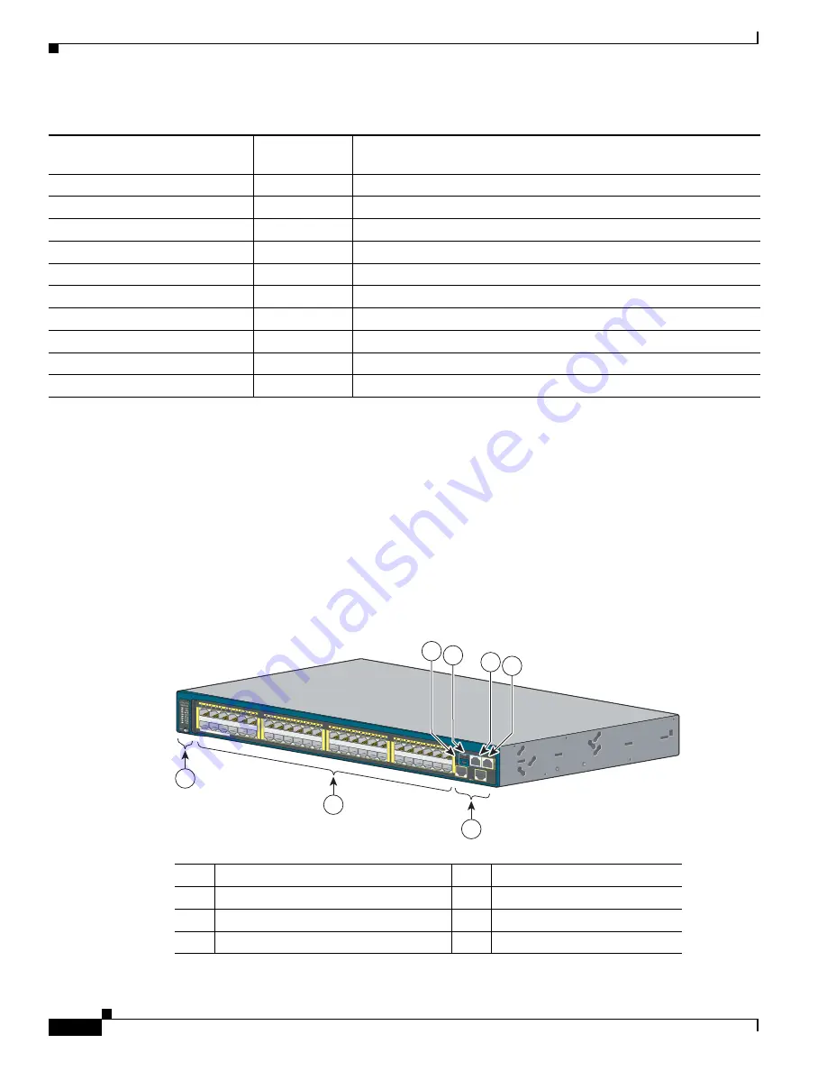
The 24- and 48-port switch front panels include the 10/100 or the 10/100/1000 Ethernet ports, or the 
10/100 or 10/100/1000 PoE ports, SFP or SFP+ module slots, the universal serial bus (USB) ports, the 
console ports, and the LEDs. All the 24- and 48-port switches have similar components. See 

Figure 1-1

Figure 1-2

Figure 1-3

, and 

Figure 1-4

 for examples.

Figure 1-1

Catalyst 2960S-48FPD-L Front Panel

Catalyst 2960S-24TS-L

1

LAN Base

24 10/100/1000 ports and 4 SFP module slots

Catalyst 2960S-48TS-S

LAN Lite

48 10/100/1000 ports and 2 SFP module slots

Catalyst 2960S-24TS-S

LAN Lite

24 10/100/1000 ports and 2 SFP module slots 

Catalyst 2960S-F48FPS-L

1

LAN Base

48 10/100 PoE+ ports (PoE budget of 740 W) and 4 SFP module slots

Catalyst 2960S-F48LPS-L

1

LAN Base

48 10/100 PoE+ ports (PoE budget of 370 W) and 4 SFP module slots

Catalyst 2960S-F48TS-L

1

LAN Base

48 10/100 ports and 4 SFP module slots

Catalyst 2960S-F24PS-L

1

LAN Base

24 10/100 PoE+ ports (PoE budget of 370 W) and 2 SFP module slots

Catalyst 2960S-F24TS-L

1

LAN Base

24 10/100 ports and 2 SFP module slots

Catalyst 2960S-F48TS-S

LAN Lite

48 10/100 ports and 2 SFP module slots

Catalyst 2960S-F24TS-S

LAN Lite

24 10/100 ports and 2 SFP module slots

1.

Support Cisco FlexStack technology.

2.

SFP+ = 10 Gigabit uplink.

3.

SFP = 1 Gigabit uplink.

Table 1-1

Switch Models and Descriptions (continued)

Switch Model

Supported 


Software Image Description

1

Mode button and switch LEDs

5

USB mini-Type B (console) port

2

10/100/1000 PoE+ ports

1

6

RJ-45 console port

3

SFP+ module slots

7

Ethernet management port

4

USB Type A port 

Catalyst 2960-S


Series 

PoE 10G

11X

2X

1X

23X

24X

25X

26X

1

2

47X

48X

POWER  

OVER  ETHERNET   740W

37X

39X

36X

38X

11X

14X

12X

13X

206693

3

1

2

4

5

6

7

Содержание Catalyst 2960-S Series

Страница 1: ...co Systems Inc 170 West Tasman Drive San Jose CA 95134 1706 USA http www cisco com Tel 408 526 4000 800 553 NETS 6387 Fax 408 527 0883 Catalyst 2960 S Switch Hardware Installation Guide August 2012 Text Part Number OL 19732 04 ...

Страница 2: ...ent is causing interference by turning it off If the interference stops it was probably caused by the Cisco equipment or one of its peripheral devices If the equipment causes interference to radio or television reception try to correct the interference by using one or more of the following measures Turn the television or radio antenna until the interference stops Move the equipment to one side or ...

Страница 3: ...100 Ports 1 6 10 100 1000 Ports 1 6 Management Ports 1 7 USB Type A Port 1 8 SFP and SFP Module Slots 1 8 LEDs 1 11 System LED 1 11 RPS LED 1 12 Master LED 1 12 Port LEDs and Modes 1 12 Stack LED 1 15 Console LEDs 1 16 Ethernet Management Port LED 1 17 Rear Panel 1 17 FlexStack Ports 1 19 RPS Connector 1 19 Cisco RPS 2300 1 19 AC Power Connector 1 20 Management Options 1 20 Network Configurations ...

Страница 4: ...RPS Connector Cover 2 15 Mounting on a Wall 2 16 Table or Shelf Mounting 2 17 After Switch Installation 2 17 Connecting the FlexStack Cables 2 17 Installing the Power Cord Retainer Optional 2 18 Installing SFP and SFP Modules 2 20 Installing an SFP or SFP Module 2 21 Removing an SFP or SFP Module 2 21 Connecting to SFP and SFP Modules 2 22 Connecting to Fiber Optic SFP and SFP Modules 2 22 Connect...

Страница 5: ...ons B 1 10 100 Ports Including PoE B 1 B 2 10 100 1000 Ports Including PoE B 2 SFP Module Connectors B 2 Cables and Adapters B 3 SFP Module Cables B 3 Cable Pinouts B 5 Console Port Adapter Pinouts B 6 A P P E N D I X C Configuring the Switch with the CLI Based Setup Program C 1 Accessing the CLI Through Express Setup C 1 Accessing the CLI Through the Console Port C 1 Connecting the RJ 45 Console ...

Страница 6: ...Contents vi Catalyst 2960 S Switch Hardware Installation Guide OL 19732 04 Entering the Initial Configuration Information C 6 IP Settings C 6 Completing the Setup Program C 6 I N D E X ...

Страница 7: ...eferences to materials not contained in this manual Caution Means reader be careful In this situation you might do something that could result in equipment damage or loss of data The safety warnings for this product are translated into several languages in the Regulatory Compliance and Safety Information for the Catalyst 2960 and 2960 S Switches that ships with the product The EMC regulatory state...

Страница 8: ...ts_support_series_home html Cisco Small Form Factor Pluggable Modules Installation Notes http www cisco com en US products hw modules ps5455 products_device_support_tables_list html Cisco Gigabit Ethernet Transceiver Modules Compatibility Matrix Cisco 100 Megabit Ethernet SFP Modules Compatibility Matrix Cisco Small Form Factor Pluggable Modules Compatibility Matrix Compatibility Matrix for 1000BA...

Страница 9: ...tware Image Description Catalyst 2960S 48FPD L1 LAN Base 48 10 100 1000 Power over Ethernet Plus PoE ports PoE budget of 740 W and 2 small form factor pluggable SFP 2 module slots Catalyst 2960S 48LPD L1 LAN Base 48 10 100 1000 PoE ports PoE budget of 370 W and 2 SFP module slots Catalyst 2960S 24PD L1 LAN Base 24 10 100 1000 PoE ports PoE budget of 370 W and 2 SFP module slots Catalyst 2960S 48TD...

Страница 10: ...W and 4 SFP module slots Catalyst 2960S F48LPS L1 LAN Base 48 10 100 PoE ports PoE budget of 370 W and 4 SFP module slots Catalyst 2960S F48TS L1 LAN Base 48 10 100 ports and 4 SFP module slots Catalyst 2960S F24PS L1 LAN Base 24 10 100 PoE ports PoE budget of 370 W and 2 SFP module slots Catalyst 2960S F24TS L1 LAN Base 24 10 100 ports and 2 SFP module slots Catalyst 2960S F48TS S LAN Lite 48 10 ...

Страница 11: ...d member port 2 Module slot numbers are 49 50 51 and 52 6 RJ 45 console port 3 SFP module slots 7 Ethernet management port 4 USB Type A port Catalyst 2960 S Series 11X 2X 1X 23X 24X 25X 26X 49 51 50 52 47X 48X POWER OVER ETHERNET 740W 37X 39X 36X 38X 11X 14X 12X 13X 3 1 2 206694 4 5 6 7 1 Mode button and switch LEDs 5 USB mini Type B console port 2 10 100 1000 ports1 1 Port numbering is from left ...

Страница 12: ...X POWER OVER ETHERNET 740W 37X 39X 36X 38X 11X 14X 12X 13X 3 1 2 344240 4 5 6 7 1 Mode button and switch LEDs 5 USB mini Type B console port 2 10 100 POE ports1 6 RJ 45 console port 3 SFP module slots 7 Ethernet management port 4 USB Type A port 1 Port numbering is from left to right with port 1 on the far left The first member of the pair port 1 is above the second member port 2 Module slot numbe...

Страница 13: ...Category 5e or Category 6 unshielded twisted pair UTP cable The 10BASE T traffic can use Category 3 or Category 4 UTP cable Cisco intelligent power management capabilities include enhanced power negotiation power reservation and per port power policing For information about configuring and monitoring PoE ports see the switch software configuration guide on Cisco com For information about port conn...

Страница 14: ...ections section on page 2 24 and Appendix B Connector and Cable Specifications Note The output of the PoE circuit has been evaluated as a Limited Power Source LPS per IEC 60950 1 10 100 Ports The 10 100 ports use RJ 45 connectors with Ethernet pinouts The maximum cable length is 328 feet 100 meters The 100BASE TX traffic requires Category 5 Category 5e or Category 6 unshielded twisted pair UTP cab...

Страница 15: ...sco Windows USB device driver you can connect and disconnect the USB cable from the console port without affecting Windows HyperTerminal operations Mac OS X or Linux require no special drivers The console output always goes to both the RJ 45 and the USB console connectors but the console input is active on only one of the console connectors at any one time The USB console takes precedence over the...

Страница 16: ...se and copy as well as the ability to format the flash device with a FAT file system For more information about the switch management ports see the switch software configuration guide and the command reference on Cisco com and the Connector and Cable Specifications section on page B 1 SFP and SFP Module Slots The switch has either two or four 1 Gigabit SFP or two 10 Gigabit SFP module slots The sl...

Страница 17: ...D L GLC BX D GLC BX U GLC ZX SM CWDM SFP 1470 CWDM SFP 1490 CWDM SFP 1510 CWDM SFP 1530 CWDM SFP 1550 CWDM SFP 1570 CWDM SFP 1590 CWDM SFP 1610 Catalyst 2960S 48FPS L Catalyst 2960S 48LPS L Catalyst 2960S 24PS L Catalyst 2960S 48TS L Catalyst 2960S 24TS L Catalyst 2960S F48FPS L Catalyst 2960S F48LPS L Catalyst 2960S F24PS L Catalyst 2960S F48TS L Catalyst 2960S F24TS L GLC FE 100BX D GLC FE 100BX...

Страница 18: ...nstalling SFP and SFP Modules section on page 2 20 For cable specifications see Appendix B Connector and Cable Specifications Table 1 3 Supported SFP Modules Switch Models Supported SFP Modules Catalyst 2960S 48FPD L Catalyst 2960S 48LPD L Catalyst 2960S 24PD L Catalyst 2960S 48TD L Catalyst 2960S 24TD L SFP 10G LR SFP 10G SR SFP 10G LRM SFP H10GB CU1M SFP H10GB CU3M SFP H10GB CU5M ...

Страница 19: ...stem LED 1 System LED 6 Speed LED 2 RPS1 LED 1 RPS redundant power system only on switch models that support RPS 7 Stack LED2 2 Only on switch models that support stacking 3 Master LED2 8 PoE LED3 3 Only on switch models that support PoE 4 Status LED 9 Mode button 5 Duplex LED Table 1 4 System LED Color System Status Off System is not powered on Green System is operating normally Amber System is r...

Страница 20: ... LED Color RPS Status Off RPS is off or not properly connected Green RPS is connected and can provide back up power Blinking green RPS is connected but is unavailable It is providing power to another device redundancy has been allocated to the other device Amber The RPS is in standby mode or in a fault condition See the RPS documentation Blinking amber The power supply in a switch has failed and t...

Страница 21: ...ne port was denied power or at least one port has a PoE fault Table 1 7 Port Mode LEDs continued Mode LED Port Mode Description Table 1 9 Meanings of LED Colors in Different Modes Port Mode Port LED Color Meaning PoE Off PoE is off If the powered device is receiving power from an AC power source the port LED is off even if the powered device is connected to the switch port Green PoE is on The port...

Страница 22: ...er Port is blocked by Spanning Tree Protocol STP and is not forwarding data After a port is reconfigured the port LED can remain amber for up to 30 seconds as STP searches the switch for possible loops Blinking amber Port is blocked by STP and is sending and receiving packets DUPLX duplex Off Port is operating in half duplex Green Port is operating in full duplex SPEED 10 100 and 10 100 1000 ports...

Страница 23: ...ck LED When you select the Stack LED the respective Stack LEDs are green when the stack ports on the switch rear panel are up and the respective Stack LEDs are amber when the ports are down SFP module port LEDs 1 and 2 on the switch show the status for stack ports 1 and 2 respectively If the port LEDs are green on all the switches in the stack the stack is operating at full bandwidth If any port L...

Страница 24: ... LED colors and their meanings 1 USB console LED 2 RJ 45 console LED Catalyst 2960 S Series PoE 10G 11X 2X 1X 23X 24X 25X 26X 1 2 47X 48X POWER OVER ETHERNET 740W 206697 Catalyst 2960 S Series PoE 10G 1 2 47X 48X 2 1 Table 1 10 RJ 45 and USB Console LEDs LED Color Description RJ 45 console port Green RJ 45 console port is active When this LED is on the USB console port LED is off Off The port is n...

Страница 25: ... connector The stacking capable switch is available with or without an RPS connector See Figure 1 10 and Figure 1 11 Figure 1 10 Catalyst 2960 S Switch Rear Panel with Stacking Module Slot and RPS connector Table 1 11 Ethernet Management Port LED Color Description Green Active link to PC Off Inactive link Amber POST failure 1 FlexStack module slot and cover 3 RPS connector 2 Fan exhaust 4 AC power...

Страница 26: ...apable switches have a fan exhaust and an AC power connector The nonstacking capable switch is available with or without an RPS connector See Figure 1 12 and Figure 1 13 Figure 1 12 Catalyst 2960 S Switch Rear Panel with an RPS connector 1 FlexStack module slot and cover 3 AC power connector 2 Fan exhaust RATING 100 240 12 6A 50 60Hz 1 2 3 344241 1 Fan exhaust 3 AC power connector 2 RPS connector ...

Страница 27: ...nonapproved Cisco cables or equipment RPS Connector Note RPS is not supported on the Catalyst 2960S F48FPS L 2960S F48LPS L 2960S F24PS L 2960S F48TS L 2960S F24TS L 2960S F48TS S and 2960S F24TS S switches The Cisco RPS 2300 model PWR RPS2300 supports the Catalyst 2960 S switch Warning Attach only the following Cisco RPS model to the RPS receptacle RPS2300 Statement 370 Connect the switch and the...

Страница 28: ...cation for LANs of small and medium sized businesses You can use the GUI to configure and manage switch clusters or standalone switches Cisco Network Assistant is available at no cost and can be downloaded from this URL http www cisco com pcgi bin tablebuild pl NetworkAssistant For information on starting the Network Assistant application see the Getting Started with Cisco Network Assistant guide ...

Страница 29: ...ormation Base MIB extensions and four Remote Monitoring RMON groups See the switch software configuration guide on Cisco com and the documentation that came with your SNMP application for information Cisco Security Manager Cisco Security Manager Security Manager manages security policies on Cisco security devices Security Manager supports integrated provisioning of firewall IPS and VPN site to sit...

Страница 30: ...1 22 Catalyst 2960 S Switch Hardware Installation Guide OL 19732 04 Chapter 1 Product Overview Management Options ...

Страница 31: ...tial switch setup assigning the switch IP address and powering on information see the switch getting started guide on Cisco com Preparing Safety Warnings page 2 1 Installation Guidelines page 2 4 Box Contents page 2 4 Tools and Equipment page 2 4 Safety Warnings This section includes the basic installation caution and warning statements Read this section before you start the installation procedure...

Страница 32: ...ains stable The following guidelines are provided to ensure your safety This unit should be mounted at the bottom of the rack if it is the only unit in the rack When mounting this unit in a partially filled rack load the rack from the bottom to the top with the heaviest component at the bottom of the rack If the rack is provided with stabilizing devices install the stabilizers before mounting or s...

Страница 33: ...electrical circuitry and be familiar with standard practices for preventing accidents Use the statement number provided at the end of each warning to locate its translation in the translated safety warnings that accompanied this device Statement 1071 Warning Voltages that present a shock hazard may exist on Power over Ethernet PoE circuits if interconnections are made using uninsulated exposed met...

Страница 34: ...y the temperature around it might be greater than normal room temperature Operating environment is within the ranges listed in Appendix A Technical Specifications Humidity around the switch does not exceed 85 percent Altitude at the installation site is not greater than 10 000 feet For 10 100 and 10 100 1000 fixed ports the cable length from a switch to a connected device cannot exceed 328 feet 10...

Страница 35: ...t representative if your switch fails POST After a successful POST unplug the power cord from the switch Install the switch in a rack on a wall on a table or on a shelf as described in the Installing the Switch section on page 2 10 If your configuration has an RPS connect the switch and the RPS to different AC power sources See the Cisco RPS documentation for information Note When you connect the ...

Страница 36: ...are Installation Guide OL 19732 04 Chapter 2 Switch Installation Planning a Switch Stack CAB STK E 0 5M 0 5 meter cable CAB STK E 1M 1 meter cable CAB STK E 3M 3 meter cable Access to the switch rear panel and to the rear of the rack ...

Страница 37: ... 1 Removing the Blank Cover Step 2 Grasp the FlexStack module on the sides and insert it into the module slot Push the module in completely until you feel it snap into place Figure 2 2 Inserting the FlexStack Module Step 3 Secure the screws tightly on each side of the module Figure 2 3 Securing the FlexStack Module Note Make sure the screws are only finger tight to avoid overtightening 206761 2067...

Страница 38: ...king Switches with the 0 5 meter FlexStack Cable Figure 2 5 Stacking Switches with 0 5 meter and 3 meter FlexStack Cables Stack Bandwidth and Partitioning Examples Figure 2 6 shows a stack that provides full bandwidth with redundant connections Figure 2 6 Stack with Full Bandwidth Connections Figure 2 7 shows a stack with incomplete stack cabling connections This stack provides only half bandwidth...

Страница 39: ...ws a stack with a bad FlexStack cable in link B This stack provides only half bandwidth and does not have redundant connections Figure 2 8 Stack with a Failover Condition Figure 2 9 shows a stack with a bad link B This stack partitions into two stacks and switch 1 and switch 3 are stack masters Figure 2 9 Partitioned Stack with a Failover Condition A B 206702 A B 206703 C A B 206704 ...

Страница 40: ...e a stack master re election or to manually elect the stack master see the Managing Switch Stacks chapter in the switch software configuration guide on Cisco com Installing the Switch Rack Mounting page 2 10 Wall Mounting page 2 14 Table or Shelf Mounting page 2 17 After Switch Installation page 2 17 Rack Mounting Installation in other than 19 inch racks requires a bracket kit not included with th...

Страница 41: ...g the Rack Mount Brackets To rack mount the switch first remove the screws from the switch chassis so that the mounting brackets can be attached Note You do not need to remove the screws for attaching the brackets in the rear mounting position Figure 2 11 Removing Screws from the Switch 206933 19 inch ETSI 252587 39X 38X 47X 48X 1 2 Catalyst 2960 S Series PoE 10G ...

Страница 42: ...r 19 inch Racks 1 Front mounting position 3 Mid mounting position 2 Number 8 Phillips flat head screws 48 0655 01 4 Rear mounting position POWER OVER ETHERN ET 740W 11X 2X 1X 11X 14X 12X 13X 23X 24X 25X 26X 37X 39X 36X 38X 47X 48X 1 2 Catalyst 2960 S Series PoE 10G Catalyst 2960 S Series PoE 10G RATING 100 240 12 6A 50 60Hz 11X 2X 1X 11X 14X 12X 13X 23X 24X 25X 26X 37X 39X 36X 38X 47X 48X 1 2 POWE...

Страница 43: ... the After Switch Installation section on page 2 17 for information on switch configuration Figure 2 13 Mounting in a Rack 1 Cable guide 4 Number 12 Phillips pan head screws 48 0523 01 2 Phillips machine screw black 48 0654 01 5 Mid mounting position 3 Front mounting position 6 Rear mounting position 11X 2X 1X 11X 14X 12X 13X 23X 24X 25X 26X 37X 39X 36X 38X 47X 48X 1 2 11X 2X 1X 11X 14X 12X 13X 23...

Страница 44: ...eginning installation Failure to use the correct hardware or to follow the correct procedures could result in a hazardous situation to people and damage to the system Statement 378 Attaching the Brackets for Wall Mounting Figure 2 14 shows how to attach a 19 inch bracket to one side of the switch Follow the same steps to attach the second bracket to the opposite side Figure 2 14 Attaching the 19 i...

Страница 45: ...connector and a cover is not needed These models do not support RPS If you are not using an RPS with your switch use the two Phillips pan head screws to attach the RPS connector cover to the back of the switch Figure 2 15 Warning If an RPS is not connected to the switch install an RPS connector cover on the back of the switch Statement 265 Figure 2 15 Attaching the RPS Connector Cover 1 Phillips p...

Страница 46: ... to a firmly attached plywood mounting backboard Mount the switch with the front panel facing up or front facing down Figure 2 16 Figure 2 16 Mounting on a Wall When you complete the switch installation see the After Switch Installation section on page 2 17 for information on switch configuration 1 User supplied screws 206705 1 1 Cat alys t 296 0 S S e ri e s P o E 1 0 G 11X 2X 1X 23X 24X 25X 26X ...

Страница 47: ... in the Related Publications section Use the CLI setup program to enter the initial switch configuration See Appendix C Configuring the Switch with the CLI Based Setup Program Connect to the stack ports See the Connecting the FlexStack Cables section on page 2 17 Install the power cord retainer optional See the Installing the Power Cord Retainer Optional section on page 2 18 Connect to the front p...

Страница 48: ...Stack cables from the connectors replace the dust covers to protect them from dust Caution Removing and installing the FlexStack cable can shorten its useful life Do not remove and insert the cable more often than is absolutely necessary Installing the Power Cord Retainer Optional The power cord retainer part number PWR CLP is optional You can order it when you order your switch or you can order i...

Страница 49: ...iner through the other latches to lock it See Figure 2 20 Figure 2 20 Locking the Retainer Step 5 Optional Use the small sleeve for thin power cords Use the small sleeve to provide greater stability for thin cords Detach the sleeve and slide it over the power cord See Figure 2 21 1 AC power cord 3 Latch 2 Smaller sleeve for thin power cords RATING 100 240 12 6A 50 60Hz 1 2 3 333872 1 AC power cord...

Страница 50: ...FP modules See the SFP and SFP Module Slots section on page 1 8 and the switch release notes on Cisco com for the list of supported SFP modules Use only Cisco SFP modules on the switch Each Cisco module has an internal serial EEPROM that is encoded with security information This encoding provides a way for Cisco to identify and validate that the module meets the requirements for the switch For inf...

Страница 51: ...ist strap to your wrist and to a bare metal surface Step 2 Find the send TX and receive RX markings on the module top On some SFP or SFP modules the send and receive TX and RX markings might be replaced by arrows that show the direction of the connection either send or receive TX or RX Step 3 If the module has a bale clasp latch move it to the open unlocked position Step 4 Align the module in fron...

Страница 52: ...r 1000BASE T SFP modules see the Connecting to 1000BASE T SFP section For instructions about how to install or remove an SFP module see the Installing SFP and SFP Modules section on page 2 20 Connecting to Fiber Optic SFP and SFP Modules Warning Class 1 laser product Statement 1008 Caution Do not remove the rubber plugs from the SFP or SFP module port or the rubber caps from the fiber optic cable ...

Страница 53: ...e See Chapter 3 Troubleshooting for solutions to cabling problems Step 5 If necessary reconfigure and restart the switch or target device Connecting to 1000BASE T SFP Caution To prevent ESD damage follow your normal board and component handling procedures Step 1 Connect one end of the cable to the SFP module port see Figure 2 25 When connecting to servers workstations and routers use a four twiste...

Страница 54: ... problems Step 4 If necessary reconfigure and restart the switch or other device 10 100 and 10 100 1000 PoE Port Connections See the 10 100 PoE Ports section on page 1 5 and the 10 100 1000 PoE Ports section on page 1 5 for information on the cables and connectors The ports provide PoE support for devices compliant with IEEE 802 3af and also provide Cisco prestandard PoE support for Cisco IP Phone...

Страница 55: ...not be turned on there might be a cable problem or there might be a problem with the adapter in the other device See Chapter 3 Troubleshooting for solutions to cabling problems Caution Noncompliant cabling or powered devices can cause a PoE port fault Use only standard compliant cabling to connect Cisco prestandard IP Phones and wireless access points or IEEE 802 3af compliant devices You must rem...

Страница 56: ... speed and duplex Set the interface speed and duplex parameters on both ends of the connection Use the guidelines in Table 2 1 to select the correct cable for connecting the switch 10 100 and 10 100 1000 ports to other devices See the Connector and Cable Specifications section on page B 1 for cable pinout descriptions Where to Go Next To change the switch settings you can use the switch default co...

Страница 57: ...t statistics from the device manager from the CLI or from an SNMP workstation See the software configuration guide the switch command reference guide on Cisco com or the documentation that came with your SNMP application for details Switch POST Results See the Verifying Switch Operation section on page 2 5 for information on POST Note POST failures are usually fatal Contact your Cisco technical su...

Страница 58: ...rnet use Category 3 copper cable for 10 Mb s UTP connections Use either Category 5 Category 5e or Category 6 UTP for 10 100 or 10 100 1000 Mb s connections For fiber optic cables verify that you have the correct cable for the distance and port type Make sure that the connected device ports both match and use the same type encoding optical frequency and fiber type For copper connections determine i...

Страница 59: ...over cable Replace the crossover cable with a straight through cable Caution Noncompliant cabling or powered devices can cause a PoE port fault Use only standard compliant cabling to connect Cisco prestandard IP Phones and wireless access points or IEEE 802 3af compliant devices You must remove any cable or device that causes a PoE fault SFP and SFP Module Use only Cisco SFP or SFP modules in the ...

Страница 60: ...nce FCS or late collisions errors this might mean a speed or duplex mismatch A common issue with speed and duplex occurs when duplex and speed settings are mismatched between two switches between a switch and a router or between the switch and a workstation or server Mismatches can happen when manually setting the speed and duplex or from autonegotiation issues between the two devices To maximize ...

Страница 61: ... and hold the Mode button Figure 1 1 on page 1 2 2 The switch LEDs blink after about 2 seconds If the switch is not configured the LEDs above the Mode button turn green You can omit the next step 3 Continue holding down the Mode button The LEDs stop blinking after 8 seconds and then the switch reboots You can now configure the switch by using Express Setup as described in the switch getting starte...

Страница 62: ...960S 24TD L 2960S 48TS L 2960S 24TS L 2960S 48TS S and 2960S 24TS S Switches Figure 3 3 Serial Number Location for the Catalyst 2960S F48FPS L 2960S F48LPS L and 2960S F24PS L Switches i Figure 3 4 Serial Number Location for the Catalyst 2960S F48TS L and 2960S F24TS L Switches 252060 781 00645 01 A0 SN XXXNNNNXXXX 333814 781 00757 01 A0 SN XXXNNNNXXXX 333781 781 00756 01 A0 SN XXXNNNNXXXX ...

Страница 63: ...apter 3 Troubleshooting Finding the Switch Serial Number Figure 3 5 Serial Number Location for the Catalyst 2960S F48TS S and 2960S F24TS S Switches Figure 3 6 Serial Number Location for the C2960S STACK Module 333813 781 00755 01 A0 SN XXXNNNNXXXX 208732 SN XXXNNNNXXXX ...

Страница 64: ...atalyst 2960 S Switch Hardware Installation Guide OL 19732 04 Chapter 3 Troubleshooting Finding the Switch Serial Number Figure 3 7 Serial Number Location for the C2960S F STACK Module 333947 SN XXXNNNNXXXX ...

Страница 65: ...Connect the switch to the stack 5 Make the same connections on the replacement switch that were on the failed switch 6 Reinstall any modules and make cable connections 7 Power on the replacement switch The replacement switch has the same configuration for all the interfaces as the failed switch and functions the same as the failed switch If you had manually set the member numbers for any stack mem...

Страница 66: ...3 10 Catalyst 2960 S Switch Hardware Installation Guide OL 19732 04 Chapter 3 Troubleshooting Replacing a Failed Stack Member ...

Страница 67: ...1 Environmental Specifications for All Catalyst 2960 S Switches Environmental Ranges Operating temperature 23 to 113 F 5 to 45 C up to 5 000 ft 1500 m 23 to 104 F 5 to 40 C up to 10 000 ft 3000 m Storage temperature 13 to 158 F 25 to 70 C Relative humidity 10 to 85 noncondensing Storage altitude Up to 15 000 ft 4573 m ...

Страница 68: ... Catalyst 2960S 48FPS L 12 V 4 A 52 V 8 A Catalyst 2960S 48LPS L 12 V 3 A 52 V 8 A Catalyst 2960S 24PS L Power consumption1 129 W 440 BTUs per hour Catalyst 2960S 48FPD L 100 W 341 BTUs per hour Catalyst 2960S 48LPD L 84 W 286 BTUs per hour Catalyst 2960S 24PD L 131 W 447 BTUs per hour Catalyst 2960S 48FPS L 61 W 208 BTUs per hour Catalyst 2960S F48FPS L 100 W 341 BTUs per hour Catalyst 2960S 48LP...

Страница 69: ...lyst 2960S 48LPS L 12 5 lb 5 66 kg Catalyst 2960S F48LPS L 12 5 lb 5 66 kg Catalyst 2960S 24PS L 12 5 lb 5 66 kg Catalyst 2960S F24PS L Dimensions H x D x W 1 75 x 15 19 x 17 5 in 4 45 x 38 6 x 44 5 cm Applies to all PoE switches 1 Power consumption values for the power consumed internally by the switch at 120 VAC 60 Hz 2 Power rating values for the switch input power Table A 2 Catalyst 2960S 48FP...

Страница 70: ...t voltage for RPS 2300 12 V 4 A Catalyst 2960S 48TD L 12 V 3 A Catalyst 2960S 24TD L 12 V 4 A Catalyst 2960S 48TS L 12 V 4 A Catalyst 2960S 24TS L 12 V 4 A Catalyst 2960S 48TS S 12 V 3 A Catalyst 2960S 24TS S Power consumption1 55 W 188 BTUs per hour Catalyst 2960S 48TD L 40 W 136 BTUs per hour Catalyst 2960S 24TD L 52 W 177 BTUs per hour Catalyst 2960S 48TS L 35 W 119 BTUs per hour Catalyst 2960S...

Страница 71: ...st 2960S 48TD L 2960S 24TD L 2960S 48TS L 2960S 24TS L 2960S 48TS S 2960S 24TS S models 1 75 x 11 77 x 17 50 in 4 45 x 29 9 x 44 5 cm Catalyst 2960S F48TS L 2960S F24TS L 2960S F48TS S and 2960S F24TS S models 1 75 x 12 37 x 17 50 in 4 45 x 31 4 x 44 5 cm 1 Power consumption values for the power consumed internally by the switch at 120 VAC 60 Hz 2 Power rating values for the switch input power Tab...

Страница 72: ...A 6 Catalyst 2960 S Switch Hardware Installation Guide OL 19732 04 Appendix A Technical Specifications ...

Страница 73: ...tor Specifications 10 100 Ports Including PoE page B 1 10 100 1000 Ports Including PoE page B 2 SFP Module Connectors page B 2 10 100 Ports Including PoE All the 10 100 ports use standard RJ 45 connectors and Ethernet pinouts Figure B 1 10 100 Port Pinouts H5318 2 3 1 4 5 6 7 8 Pin Label 1 2 3 4 5 6 7 8 RD RD TD NC NC TD NC NC ...

Страница 74: ...ns 10 100 1000 Ports Including PoE All the 10 100 1000 ports use standard RJ 45 connectors and Ethernet pinouts Figure B 2 10 100 1000 Port Pinouts SFP Module Connectors Figure B 3 Duplex LC Cable Connector Figure B 4 Simplex LC Cable Connector 60915 2 3 1 4 5 6 7 8 Pin Label 1 2 3 4 5 6 7 8 TP0 TP0 TP1 TP2 TP2 TP1 TP3 TP3 58476 57834 ...

Страница 75: ...s up to 328 feet 100 meters 60915 2 3 1 4 5 6 7 8 Pin Label 1 2 3 4 5 6 7 8 TP0 TP0 TP1 TP2 TP2 TP1 TP3 TP3 Table B 1 Fiber Optic SFP Module Port Cabling Specifications SFP Module Wavelength nanometers Cable Type Core Size Cladding Size micron Modal Bandwidth MHz km 1 Cable Distance 100BASE BX GLC FE 100BX D GLC FE 100BX U 1310 TX 1550 RX SMF G 6522 32 810 feet 10 km 100BASE FX GLC GE 100FX 1310 M...

Страница 76: ...0 125 50 125 160 200 400 500 2000 722 feet 220 m 722 feet 220 m 328 feet 100 m 722 feet 220 m 722 feet 220 m 10GBASE CX1 SFP H10GB CU1M SFP H10GB CU3M SFP H10GB CU5M Twinax cable 30 AWG cable assembly Twinax cable 30 AWG cable assembly Twinax cable 24 AWG cable assembly 3 feet 1 m 9 feet 3 m 16 feet 5 m 1 Modal bandwidth applies only to multimode fiber 2 A mode field diameter cladding diameter 9 m...

Страница 77: ...e Schematic 4 1000BASE ZX SFP modules can send data up to 62 miles 100 km by using dispersion shifted SMF or low attenuation SMF the distance depends on the fiber quality the number of splices and the connectors 1 TPO 2 TPO 3 TP1 6 TP1 1 TP1 Switch Router or PC 2 TP1 3 TPO 6 TPO 4 TP2 5 TP2 7 TP3 8 TP3 4 TP3 5 TP3 7 TP2 8 TP2 65272 1 TP0 2 TP0 3 TP1 6 TP1 1 TP0 Switch Switch 2 TP0 3 TP1 6 TP1 4 TP...

Страница 78: ...sole port to a console PC You need to provide a RJ 45 to DB 25 female DTE adapter to connect the switch console port to a terminal You can order the kit part number ACS DSBUASYN from Cisco Switch 3 TD 6 TD 1 RD 2 RD Switch 3 TD 6 TD 1 RD 2 RD H5579 Pin 1 H10632 Pin 8 Pin 1 on one connector and pin 8 on the other connector should be the same color Table B 2 Console Port Signaling with a DB 9 Adapte...

Страница 79: ...nnector and Cable Specifications Cables and Adapters Table B 3 Console Port Signaling with a DB 25 Adapter Switch Console Port DTE RJ 45 to DB 25 Terminal Adapter Console Device Signal DB 25 Pin Signal RTS 5 CTS DTR 6 DSR TxD 3 RxD GND 7 GND GND 7 GND RxD 2 TxD DSR 20 DTR CTS 4 RTS ...

Страница 80: ...B 8 Catalyst 2960 S Switch Hardware Installation Guide OL 19732 04 Appendix B Connector and Cable Specifications Cables and Adapters ...

Страница 81: ...EXEC command Enter the information described in the IP Settings section on page C 6 and the Completing the Setup Program section on page C 6 After you have entered the configuration information for the switch save it to flash memory by using the write memory privileged EXEC command Note In Express Setup mode the IP address 10 0 0 1 remains active on the switch until you enter the write memory comm...

Страница 82: ...Microsoft Windows Vista USB Driver section on page C 4 Note If you do not want to use the switch USB console port you can use an RJ 45 to DB 9 adapter cable to connect the switch RJ 45 console port to a PC or terminal port Figure C 1 Connecting the USB Console Cable to the Catalyst 2960 S Switch Step 2 Start the terminal emulation program on the PC or the terminal The program frequently a PC appli...

Страница 83: ...nected to the switch USB console port Installing the Cisco Microsoft Windows XP USB Driver Step 1 Obtain the file Cisco_usbconsole_driver zip from the Cisco com web site and unzip it Note You can download the driver file from the Cisco com site where you download the switch software Step 2 If using 32 bit Windows XP double click the file setup exe from the Windows_32 folder If using 64 bit Windows...

Страница 84: ... complete the driver installation The USB console is ready for use Installing the Cisco Microsoft Windows Vista USB Driver Step 1 Obtain the file Cisco_usbconsole_driver zip from the Cisco com web site and unzip it Note You can download the driver file from the Cisco com site where you download the switch software Step 2 If using 32 bit Windows Vista double click the file setup exe from the Window...

Страница 85: ...er Step 1 Run setup exe for Windows 32 bit or setup x64 exe for Windows 64bit Click Next Step 2 The InstallShield Wizard for Cisco Virtual Com appears Click Next Step 3 When the Program Maintenance window appears select the Remove radio button Click Next Step 4 When the Remove the Program window appears click Remove Step 5 When the InstallShield Wizard Completed window appears click Finish Uninsta...

Страница 86: ...l switches in the stack the initial setup dialog appears at the console where you first press Enter Step 1 Enter Yes at these two prompts Would you like to enter the initial configuration dialog yes no yes At any point you may enter a question mark for help Use ctrl c to abort configuration dialog at any prompt Default settings are in square brackets Basic management setup configures only enough c...

Страница 87: ...the interface by entering the switch IP address and subnet mask and pressing Return The IP address and subnet masks shown are examples Configuring interface vlan1 Configure IP on this interface yes yes IP address for this interface 10 4 120 106 Subnet mask for this interface 255 0 0 0 255 0 0 0 Step 9 Enter Y to configure the switch as the cluster command switch Enter N to configure it as a member...

Страница 88: ...OS command prompt without saving this config 1 Return back to the setup without saving this config 2 Save this configuration to nvram and exit Choose 2 to save the configuration to NVRAM to use it the next time the switch reboots Enter your selection 2 2 Make your selection and press Return The switch now runs this default configuration If you want to change this configuration or perform other man...

Страница 89: ...ault setting 2 25 troubleshooting 3 4 B brackets See mounting brackets C cable guide attaching 2 13 cables crossover four twisted pair pinout B 5 two twisted pair pinout B 5 recommended 2 25 SFP modules 1000BASE T module 2 23 stack cable part numbers 1 19 straight through four twisted pair pinout B 5 two twisted pair pinout B 5 cables caution 1 19 cabling auto MDIX 2 23 cautions i vii PoE faults 1...

Страница 90: ...g 24 and 48 port switches 2 2 ethernet management port LED 1 17 Express Setup accessing CLI by using C 1 for initial switch configuration 2 17 using to clear switch IP address 3 5 F features 1 2 to 1 20 FlexStack cable 2 5 FlexStack module 2 7 FlexStack Ports connecting 2 17 overview 1 19 front panel clearance 2 4 LEDs 1 11 to 1 15 PoE ports 1 5 1 6 SFP and SFP slots 1 8 USB ports 1 3 1 4 G ground...

Страница 91: ... mounting 2 17 wall mounting 2 14 N network configurations 1 21 noise electrical 2 4 O outside connections warning 2 3 P pinouts 10 100 1000 PoE ports B 2 adapters B 6 to B 7 console port B 7 crossover cable B 6 crossover cables four twisted pair B 5 two twisted pair B 5 RJ 45 to DB 25 terminal adapter B 7 RJ 45 to DB 9 terminal adapter B 6 SFP module ports B 2 straight through cables four twisted...

Страница 92: ...ment warning 1 19 2 2 2 5 connecting to 2 5 connector 1 19 connector cover warning 2 2 2 15 LED 1 12 S safety 2 1 serial number location 3 5 servicing equipment warning 2 3 SFP and SFP modules bale clasp latch removal 2 22 connecting to 2 22 to 2 24 connectors B 2 described 1 8 installation 2 20 to 2 22 supported 1 8 shelf mounting 2 17 Simple Network Management Protocol See SNMP SNMP network mana...

Страница 93: ...nd autonegotiation 3 4 switch performance 3 4 with LEDs 3 1 U uninstalling the Cisco Microsoft Windows USB driver C 5 USB console port connecting C 1 installing drivers C 3 overview 1 7 USB Type A interface 1 8 W wall mounting 2 14 warnings attaching the Cisco RPS 1 19 2 2 2 5 Class 1 laser 2 2 code compliance 2 3 connecting outside of building 2 3 connecting the power 2 2 defined i vii disposal o...

Страница 94: ...Index IN 6 Catalyst 2960 S Switch Hardware Installation Guide OL 19732 04 ...

Отзывы: