background image

Cisco Systems, Inc.

All contents are Copyright © 2003 Cisco Systems, Inc. All rights reserved. Important Notices and Privacy Statement.

Page 23 of 29

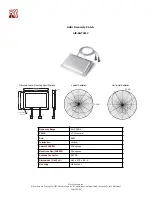
8.5 dBi Patch

AIR-ANT3549

Dimensions and Mounting Specifications

Vertical Radiation

Horizontal Radiation

Frequency Range

2.4-2.5GHz

VSWR

2:1 Max, 1.5:1 Nominal

Gain

8.5dBi

Polarization

Vertical

Azimuth 3dB BW

60 degrees

Elevations 3dB BW

55 degrees

Antenna Connector

RP-TNC

Dimensions (H x W x D)

4.88 x 4.88 x .6 in.

Mounting

Wall mount

4.88

"

4.88

"

0.66

"

8.5 dBi

8.5 dBi

Содержание Aironet 2 dBi Diversity Omnidirectional Ceiling Mount Antenna AIR-ANT5959

Страница 1: ...s installation scenarios regulatory information and technical specifications and diagrams of the available antennas Overview of Antennas Each Cisco Aironet radio product is designed to perform in a variety of environments Implementing the antenna system can greatly improve coverage and performance To optimize the overall performance of a Cisco wireless LAN it is important to understand how to maxi...

Страница 2: ...IEEE 802 11a HIPERLAN 1 and HIPERLAN 2 This band is also known as the UNII band Each range has different characteristics The lower frequencies exhibit better range but with limited bandwidth and hence lower data rates The higher frequencies have less range and subject to greater attenuation from solid objects Direct Sequence Spread Spectrum The Direct Sequence DS Spread Spectrum approach involves ...

Страница 3: ... is 360 degrees in the horizontal plane and 75 degrees in the vertical plane assuming the dipole antenna is standing vertically and resembles a donut in shape Because the beam is slightly concentrated dipole antennas have a gain over isotropic antennas of 2 14 dB in the horizontal plane Dipole antennas are said to have a gain of 2 14 dBi in comparison to an isotropic antenna Some antennas are rate...

Страница 4: ... directional antenna increases the angle of radiation usually decreases providing a greater coverage distance but with a reduced coverage angle Directional antennas include yagis patch antennas and parabolic dishes Parabolic dishes have a very narrow RF energy path and the installer must be accurate in aiming these at each other Figure 2 Directional Patch Antenna Figure 3 YAGI Antenna Diversity An...

Страница 5: ...o in receive mode will continually switch between antennas listening for a valid radio packet After the beginning sync of a valid packet is heard the radio will evaluate the sync signal of the packet on one antenna then switch to the other antenna and evaluate Then the radio will select the best antenna and use only that antenna for the remaining portion of that packet On transmit the radio will s...

Страница 6: ...less LANs want to locate the access points in the wiring closet and connect the antenna via RF coax Antenna cable introduces losses in the antenna system on both the transmitter and the receiver As the length of cable increases so does the amount of loss introduced To operate at optimum efficiency cable runs should be kept as short as possible See the section on cabling later in this document Buil...

Страница 7: ... so that their main radiated power lobes are directed at each other With a line of site configuration distances of up to 25 miles at 2 4GHz can be reached using parabolic dish antennas if a clear line of site is maintained With the use of directional antennas you are subject to fewer interference possibilities and less likely to cause interference to anyone else Point to Multipoint Bridge In this ...

Страница 8: ...ped with a drop ceiling cross member attachment The 21 dBi Parabolic Dish mounts to a 1 625 to a 2 375 mast Fine threaded turnbuckles allow accurate aiming of the antenna Lightning Arrestors When using outdoor antenna installations it is always possible that an antenna will suffer damage from potential charges developing on the antenna and cable or surges induced from nearby lightning strikes The ...

Страница 9: ...re 5 Understanding RF Power Values Radio Frequency signals are subject to various losses and gains as they pass from transmitter through cable to antenna through air or solid obstruction to receiving antenna cable and receiving radio With the exception of solid obstructions most of these figures and factors are known and can be used in the design process to determine whether an RF system such as a...

Страница 10: ...s there is clear line of sight between the two antennas with sufficient clearance for the Fresnel zone For line of sight you should be able to visibly see the remote locations antenna from the main site Longer distance may require the use of binoculars There should be no obstructions between the antennas themselves This includes trees buildings hills and so on As the distance extends beyond 6 mile...

Страница 11: ...tes the Fresnel zone and maximum range based upon cable types and lengths transmitter and receiver models and antennas The utility can be found at www cisco com go aironet calculation Note that as path loss increases and distance decreases with frequency these distances are only applicable to the 2 4 GHz band A 10dB fade margin is included for dependable communications in all weather conditions Th...

Страница 12: ...aximum power the maximum antenna gain is 6dBi However the regulations also define the maximum values in regards to the following two different system scenarios In Point to Multipoint systems the FCC has limited the maximum EIRP effective isotropic radiated power to 36dBm EIRP TX power antenna gain For every dB that the transmitter power is reduced the antenna may be increased by 1dB 29dBm TX 7dB a...

Страница 13: ...t The ETSI regulations specify maximum EIRP as 20dBm Since this includes antenna gain this limits the antennas that can be used with a transmitter To use a larger antenna the transmitter power must be reduced so that the overall gain of the transmitter plus the antenna gain less any losses in coax is equal to or less than 20dBm This drastically reduces the overall distance an outdoor link can oper...

Страница 14: ...nnels permitted in the corresponding approval areas Table 4 DSSS PHY Frequency Channel Plan Regulatory Domain Channel Frequency MHz Americas A EMEA E Israel I Japan J 1 2412 X X X 2 2417 X X X 3 2422 X X X X 4 2427 X X X X 5 2432 X X X X 6 2437 X X X X 7 2442 X X X X 8 2447 X X X X 9 2452 X X X X 10 2457 X X X 11 2462 X X X 12 2467 X X 13 2472 X X 14 2484 X Channels 2 402 GHz 2 483 GHz 1 2 3 4 5 6...

Страница 15: ...dBi It comes with a clip that allows it to be mounted to a drop ceiling cross member 5 2dBi AIR ANT4941 Omni directional Single dipole antenna with an RP TNC connector The antenna provides indoor omni directional coverage and is for use in the 2400 2500 MHz frequency band It has a 90 articulation radius It is for use with all radios that utilize an RP TNC antenna connector 2 2 dBi AIR ANT3549 Patc...

Страница 16: ...bolic reflector and feed antenna The antenna features a rugged mount It also offers 20 degree fine adjustment for both horizontal and vertical planes The antenna is provided with hardware for mast mounting 21dBi Cisco Part Number Type of Cable Description Loss 2 4GHz AIR CAB020LL R Interconnect 20 ft low loss cable with RP TNC connectors 1 3 dB AIR CAB050LL R Interconnect 50 ft low loss cable with...

Страница 17: ...iversity Dipole for use with LMC cards AIR ANT3351 Dimensions and Mounting Specifications Vertical Radiation Frequency Range 2 4 2 483GHz VSWR Less than 2 1 Gain 2 14 dBi Polarization Linear Azimuth 3dB BW Omni directional Elevations 3dB BW 80 degrees Antenna Connector MMCX 2 Dimensions H x W x D 6 5 x 7 0 x 2 12 in 6 5 7 0 Cable length 36 2 12 2 14 dBi ...

Страница 18: ...IR ANT5959 Dimensions and Mounting Specifications Vertical Radiation Frequency Range 2 4 2 5GHz VSWR 1 7 1 Power 5 watts Gain 2dBi Polarization Vertical linear Azimuth 3dB BW Omni directional Elevations 3dB BW 80 degrees Antenna Connector RP TNC Dimensions H x W x D 5 3 x 2 8 x 0 9 in Mounting Drop ceiling cross member mount 2 8 0 9 5 3 Ceiling Bracket shown for reference 2 0 dBi ...

Страница 19: ...2 Dimensions and Mounting Specifications Vertical Radiation Horizontal Radiation Frequency Range 2 4 2 5GHz VSWR 1 7 1 Nominal Gain 6dBi Polarization Vertical Azimuth 3dB BW 80 degrees Elevations Plan 3dB BW 55 degrees Antenna Connector RP TNC Dimensions H x W x D 6 65 x 4 78 x 82 in Mounting Wall mount 6 21 32 0 173ø THRU 4 PLACES 6 1 8 0 82 4 25 32 4 1 4 5 2 dBi 5 2 dBi ...

Страница 20: ...29 5 2dBi Pillar Mount Diversity Omni AIR ANT3213 Dimensions and Mounting Specifications Vertical Radiation Pattern Frequency Range 2 4 2 83GHz VSWR 2 1 Nominal Gain 5 2dBi Polarization Vertical Azimuth 3dB BW Omni directional 360 degree Elevation 3dB BW 25 degrees Antenna Connector RP TNC Dimensions H x W x D 12 x 5 x 1 in 5 12 1 5 2 dBi ...

Страница 21: ...imensions and Mounting Specifications Vertical Radiation Pattern Frequency Range 2 4 2 83GHz VSWR Less than 2 1 1 5 1 Nominal Gain 5 2dBi Polarization Vertical Azimuth 3dB BW Omni directional 360 degrees Elevations Plan 3dB BW 50 degrees Antenna Connector RP TNC Dimensions H x W 9 x 1 25 in Mounting Drop ceiling cross member indoor only 9 0 Attaches to Ceiling Cross Member 5 2 dBi ...

Страница 22: ...2dBi Standard Dipole AIR ANT4941 Dimensions and Mounting Specifications Vertical Radiation Frequency Range 2 4 2 484GHz VSWR Less than 2 1 Power 5 watts Gain 2 dBi Polarization Linear Azimuth 3dB BW Omni directional Elevations 3dB BW 70 degrees Antenna Connector RP TNC Dimensions H x W x D See Drawing Mounting Wall mount 4 5 RP TNC 1 2 14 dBi ...

Страница 23: ...tch AIR ANT3549 Dimensions and Mounting Specifications Vertical Radiation Horizontal Radiation Frequency Range 2 4 2 5GHz VSWR 2 1 Max 1 5 1 Nominal Gain 8 5dBi Polarization Vertical Azimuth 3dB BW 60 degrees Elevations 3dB BW 55 degrees Antenna Connector RP TNC Dimensions H x W x D 4 88 x 4 88 x 6 in Mounting Wall mount 4 88 4 88 0 66 8 5 dBi 8 5 dBi ...

Страница 24: ...6dBi Patch AIR ANT1729 Dimensions and Mounting Specifications Vertical Radiation Horizontal Radiation Frequency Range 2 4 2 5GHz VSWR Less than 2 1 Gain 6dBi Polarization Linear Azimuth 3dB BW 65 degrees Elevations Plan 3dB BW 70 degrees Antenna Connector RP TNC Dimensions H x W x D See Drawing Mounting Wall mount 3 75 5 5 0 5 5 2 dBi 5 2 dBi ...

Страница 25: ...nd Mounting Specifications Vertical Radiation Pattern Frequency Range 2 4 2 83GHz VSWR Less than 2 1 1 5 1 Nominal Gain 5 2dBi Polarization Vertical Azimuth 3dB BW Omni directional 360 degrees Elevations Plan 3dB BW 50 degrees Antenna Connector RP TNC Dimensions H x W 11 5 x 1 125 in Mounting Mast mount indoor outdoor 11 5 1 Polycarbonate 1 125 Aluminium Mounting Clamps Mast Cable 5 2 dBi ...

Страница 26: ...ensions and Mounting Specifications Vertical Radiation Pattern Frequency Range 2 4 2 83GHz VSWR 2 1 Nominal Gain 12dBi Polarization Vertical Azimuth 3dB BW Omni directional 360 degree Elevation 3dB BW 7 degrees Antenna Connector RP TNC Dimensions H x W 40 x 1 25 in Wind Rating 100MPH 34 6 39 5 1 25 0 1 1 0 0 1 12 Inch Pigtail RG 8 Reverse PolarityTNC Plug Male 12 dBi ...

Страница 27: ...Horizontal Radiation Pattern Vertical Radiation Pattern Frequency Range 2 4 2 83GHz VSWR Less than 2 1 1 5 1 Nominal Gain 13 5 Front to Back Ratio Greater than 30dB Polarization Vertical Azimuth 3dB BW 30 degrees Elevations 3dB BW 25 degrees Antenna Connector RP TNC Dimensions H x W 18 x 3 in Wind Rating 110MPH 3 Direction of Signal Mast 1 125 to 1 25 13 5dBYagi 2 4GHz Connector RPTNC 18 13 5 dBi ...

Страница 28: ...and Mounting Specifications Radiation Pattern Frequency Range 2 4 2 83GHz VSWR Less than 1 8 1 15 1 Nominal Power 5 watts Gain 21dBi Front to Back Ratio Greater than 25dB Maximum Side Lobe 17dB Polarization Vertical Azimuth 3dB BW 12 4 degrees Elevation 3dB BW 12 4 degrees Antenna Connector RP TNC Dimensions H x W 24 x 15 5 in Wind Rating 110MPH 8 1 2 COAX 10 1 2 REF 5 8 1 2 24 20 dBi ...

Страница 29: ... o o f fi c e s Argentina Australia Austria Belgium Brazil Bulgaria Canada Chile China PRC Colombia Costa Rica Croatia Czech Republic Denmark Dubai UAE Finland France Germany Greece Hong Kong SAR Hungary India Indonesia Ireland Israel Italy Japan Korea Luxembourg Malaysia Mexico The Netherlands New Zealand Norway Peru Philippines Poland Portugal Puerto Rico Romania Russia Saudi Arabia Scotland Sin...

Отзывы: