5
Cisco Aironet Series 1700/2700/3700 Access Point Deployment Guide
Cisco Aironet Series 3700 Access Point
Figure 73
Coverage is Optimized for Ceiling Placement and Radiates Omni-Directionally
If the AP is not mounted on the ceiling but rather on a wall, this may be acceptable for smaller deployments such as hotspots,
kiosks, transportation or smaller coverage areas. But, in an enterprise deployment it could cause excessive roams because the
signal (think of the diagram above turned on its side) can radiate on the floor above and below rather than downward in a
uniform 360 pattern.
If the module is installed in an AP 3600e (with external antennas), the 802.11ac module will still behave as described in
Figure 73
and if the dipole antennas are used, the AP will continue to provide an omni-directional coverage pattern. If a patch
or other directional or high gain antenna is used, it can create a condition where you have two different coverage patterns.
Because both the 5 GHz module radio and the internal 5 GHz 802.11n radio work together as one “blended” radio, it is best to
keep cells uniform by using dipoles or by verifying if coverage is acceptable for your intended application.
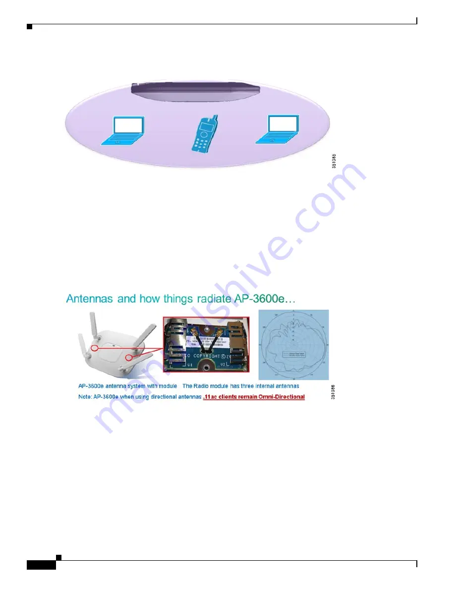
Figure 74
Module Antennas are Internal to the Access Point and Radiate Omni-Directionally
Because the 5 GHz module operates in the same frequency band as the internal 5 GHz 802.11n radio, both radios have been
purposefully designed to work in tandem (think of it as a blended radio) where both radios work as one radio, maintaining
proper isolation and performance. Unlike the competition, this allows the 802.11ac client to be serviced by the module while
legacy a/g and 802.11n clients are serviced by the integrated radios taking full advantage of ClientLink 2.0 to beam form
without having to try and bounce clients around based on signal strength.
Given the AP has a dual core processor with one core managing the module which is similar to the “master/slave” approach
that was used with IDE hard drives, the module always takes its direction from the “master” radio, in this case, the integrated
802.11n radio. So, when performing power and frequency selection, for example selecting 80 MHz (802.11ac) channel
bonding, the integrate radio and not the module radio sets the “anchor” point where the frequency starts with the module
performing the overlay extending the 80 MHz over the existing channel selected by the integrated “master” radio (802.11n
radio). Both the integrated radio and the module also share the same SSIDs.
This virtual radio approach requires both radios to be enabled. You cannot disable the integrated 5 GHz radio and just run the
.11ac radio module.


