Cisco aironet 1524SB Скачать руководство пользователя страница 12

12

OL-19762-01

  Cisco Aironet 1524SB Outdoor Mesh Access Point Hardware Addendum

Verifying Controller Association

To verify that your access point is associated to the controller, follow these steps:

Step 1

Log into your controller web interface using a web browser.

You can also use the controller CLI 

show ap summary

 command from the controller console port.

Step 2

Click 

Wireless, 

and verify that your access point MAC address is listed under Ethernet MAC.

Step 3

Log out of the controller, and close your web browser.

Using the Reset Button

The access point has a reset button located on the bottom of the unit (see 

Figure 5

). The reset button is 

recessed in a small hole that is sealed with a screw and a rubber gasket. The reset button can be used to 
perform these functions:

Reset (power cycle) the access point—press the reset button for less than 10 seconds.The LEDs turn 
off for 5 seconds and then resume normal indication.

Disable battery backup power—press the reset button for more than 10 seconds. The LEDs turn off 
for 5 seconds, turn back on for 5 seconds, then turn off and stay off.
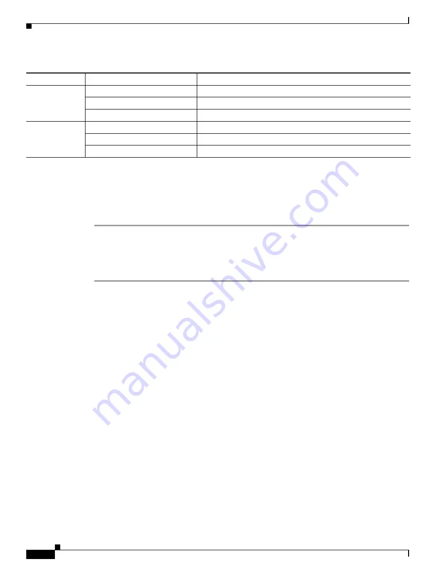
RF-1
(2.4- GHz radio)

Off

Radio turned off. 

Green

Radio is operational.

Red

Firmware failure. Contact your support organization for assistance.

RF-2 
(5.8-GHz radios)

Off

Radio turned off.

Green

Radio is operational.

Red

Firmware failure. Contact your support organization for assistance.

1.

If all LEDs are off, the access point has no power.

2.

When the access point power supply is initially turned on, all LEDs are amber.

Table 3

Access Point LED Signals (continued)

LED

Color

1, 2

Meaning

Содержание aironet 1524SB

Страница 1: ... 3 Installing the Access Point page 5 Troubleshooting page 10 Overview The Cisco Aironet 1524SB Series Outdoor Mesh Access Point is a modular design that supports up to four radios two 802 11a 5 4 to 5 8 GHz radios for backhaul and access and one 802 11b g 2 4 GHz radio for access The project access point features include Cisco IOS Dual backhaul Improved radio performance 5 levels of transmit powe...

Страница 2: ...ess point and mesh network Note The view must be identified when viewing an illustration in order to determine correct antenna port location This section refers to a radio side view in some of the illustrations The access point has two covers a radio cover and a power cable fiber cover The non hinged cover is the radio side Figure 1 identifies the access point bottom connectors radio side view Fig...

Страница 3: ...Table 1 identifies the antennas that can be used with the access point 1 Antenna port 3 4 Ground screw holes 2 Antenna port 2 5 DC power connector 3 Antenna port 1 1 2 3 4 5 203823 Table 1 Antenna Compatibility Chart Part Number Description Gain dBi AIR ANT5180V N 5 GHz compact omnidirectional 8 AIR ANT58G10SSA N 5 GHz sector 9 5 AIR ANT2450V N 2 4 GHz compact omnidirectional 5 AIR ANT2480V N 2 4 ...

Страница 4: ...hassis 1 Antenna port 1 5 Hinges 2 Antenna port 2 6 Antenna port 5 3 Antenna port 3 7 Antenna port 6 4 Antenna port 4 Table 2 Antenna Port Functions and Type Antenna Function Antenna Port 1 Antenna Port 2 Antenna Port 3 Antenna Port 4 Antenna Port 5 Antenna Port 6 3 Radio MAP DL UA OMNI NA DIR 2 4 ACCTXRX 2 4 RX 2 4 RX UL DIR 3 Radio RAP 5 8 ACC OMNI NA DIR 2 4 ACCTXRX 2 4 RX 2 4 RX DL OMNI Key AC...

Страница 5: ...ed for such use Statement 364 Warning This equipment must be externally grounded using a customer supplied ground wire before power is applied Contact the appropriate electrical inspection authority or an electrician if you are uncertain that suitable grounding is available Statement 366 Warning Read the installation instructions before connecting the system to the power source Statement 1004 Warn...

Страница 6: ...anufacturer Dispose of used batteries according to the manufacturer s instructions Statement 1015 Warning A readily accessible two poled disconnect device must be incorporated in the fixed wiring Statement 1022 Warning To reduce the risk of fire use only No 26 AWG or larger telecommunication line cord Statement 1023 Warning This unit might have more than one power supply connection All connections...

Страница 7: ...ly the same height We recommend installing the access points no higher than 40 feet 12 2 meters to allow support for wireless clients on the ground in the immediate vicinity of the access point for example directly below the access point Note To calculate path loss and to determine how far apart to install access points consult an RF planning expert Site Surveys Every network application is a uniq...

Страница 8: ... Wireless Control System Configuration Guide Release 5 0 Troubleshooting a Mesh Network These documents are available on cisco com Follow these steps to download them Step 1 Browse to http www cisco com Step 2 Click Products and Services A drop down window appears Click Wireless The Wireless Introduction page appears Step 3 Scroll down and click the Outdoor Wireless link under the Network Solution...

Страница 9: ... Ensure that all items listed in Package Contents are included in the shipment If any item is damaged or missing notify your authorized Cisco sales representative Package Contents Each access point package contains the following items Access point Cisco product documentation and translated safety warnings Grounding lug with two screws and lock washers Three liquid tight adapters Two pin DC power c...

Страница 10: ... to 0 35 in 0 51 to 0 89 cm diameter Optional cable Stinger connector Optional ground rod as required by local regulations Optional ladder power lift rope or other tools as required Note Refer to the Cisco Aironet 1520 Series Outdoor Mesh Access Point Hardware Installation Guide or Cisco Aironet 1520 Series Outdoor Mesh Access Point Mounting Instructions for specific installation and configuration...

Страница 11: ... in slot 1 5 8 GHz The slot 3 5 8 GHz radio is disabled for this project phase Table 3 Access Point LED Signals LED Color1 2 Meaning Status Off Green Access point is operational Blinking green Download or upgrade of Cisco IOS image file in progress Amber Mesh neighbor access point discovery in progress Blinking amber Mesh authentication in progress Blinking red green amber LWAPP discovery in progr...

Страница 12: ...aled with a screw and a rubber gasket The reset button can be used to perform these functions Reset power cycle the access point press the reset button for less than 10 seconds The LEDs turn off for 5 seconds and then resume normal indication Disable battery backup power press the reset button for more than 10 seconds The LEDs turn off for 5 seconds turn back on for 5 seconds then turn off and sta...

Страница 13: ...and replace the reset button cover follow these steps Step 1 Use a Phillips screwdriver to remove the reset button cover Be careful not to lose the screw and rubber gasket Step 2 Use a straightened paper clip to perform the intended action reset the access point or disable the battery Step 3 Replace the rubber gasket and start the reset button cover into the threaded hole Step 4 Use a Phillips scr...

Страница 14: ...g the Meeting To You Catalyst CCDA CCDP CCIE CCIP CCNA CCNP CCSP CCVP Cisco the Cisco Certified Internetwork Expert logo Cisco IOS Cisco Press Cisco Systems Cisco Systems Capital the Cisco Systems logo Cisco Unity Collaboration Without Limitation EtherFast EtherSwitch Event Center Fast Step Follow Me Browsing FormShare GigaDrive HomeLink Internet Quotient IOS iPhone iQuick Study IronPort the IronP...

Отзывы: