background image

3-11

Cisco 7609 Internet Router Installation Guide

OL-5079-04

Chapter 3      Installing the Cisco 7609 Internet Router

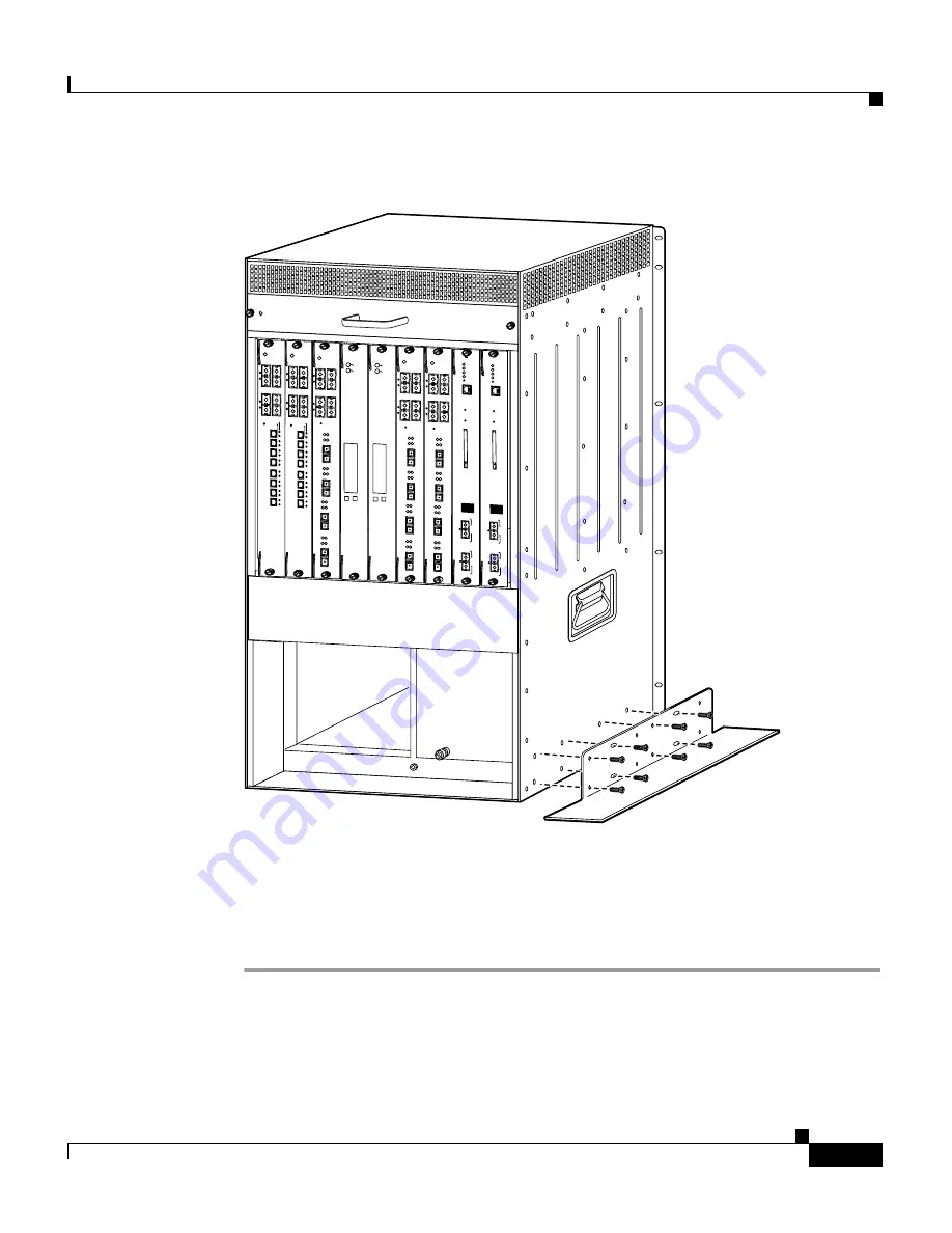
Installing the Stabilizer Kit

Figure 3-5

Installing the Stabilizer Brackets

Step 3

Tilt the chassis to the other side.

Step 4

Attach the second stabilizer bracket to the other side of the chassis with eight M4 
screws.

Step 5

Lower the chassis so that it rests on both stabilizer brackets.

FAN

STATUS

55841

SUPERVISOR2

WS-X6K-SUP2-2GE

S

TA

TU

S

SY

STE

M

C

ON

SO

LE

PW

R M

G

M

T

R

ES

ET

C

O

N

S

O

L

E

C

O

N

S

O

L

E

P

O

R

T

M

O

D

E

P

C

M

C

IA

E

J

E

C

T

P

O

R

T

 1

P

O

R

T

 2

S

w

itc
h


 L

o

a

d


1

0

0

%

1

%

LIN

K

LIN

K

SUPERVISOR2

WS-X6K-SUP2-2GE

ST

A

T

US

S

YST

E

M

C

O

N

SO

LE

P

W

R

 M

G

M

T

R

ES

ET

C

O

N

S

O

L

E

C

O

N

S

O

L

E

P

O

R

T

M

O

D

E

P

C

M

C

IA

E

J

E

C

T

P

O

R

T

 1

P

O

R

T

 2

S

w

itc
h


  L
o

a

d


1

0

0

%

1

%

LIN

K

LIN

K

S

W

IT

C

H

 F

A

B

R

IC

 M

D

L

ST

AT

US

SE

LEC

T

NEX

T

W

S

-C

6

5

0

0

-S

F

M

AC

TIV

E

S

W

IT

C

H

 F

A

B

R

IC

 M

D

L

STA

TUS

SELECT

NEX

T

W

S

-C

6

5

0

0

-S

F

M

ACT

IV

E

O

C

1

2

 P

O

S

 M
M

O

S

M

-4

0

C

1

2

-P

O

S

-M

M

STA

TUS

1

2

3

4

R

E

S

E

T

LINK

1

LIN

K

2

LIN

K

3

LIN

K

4

C

A

R

R

IE

R

A

LA

R

M

A

C

TIV

E

TX

R

X

TX

P

O

R

T 1

R

X

C

A

R

R

IE

R

A

LA

R

M

A

C

TIV

E

TX

R

X

TX

P

O

R

T 2

R

X

C

A

R

R

IE

R

A

LA

R

M

A

C

TIV

E

TX

R

X

TX

P

O

R

T 3

R

X

C

A

R

R

IE

R

A

LA

R

M

A

C

TIV

E

TX

R

X

TX

R

X

O

C

1

2

 P

O

S

 M
M

O

S

M

-4

0

C

1

2

-P

O

S

-M
M

ST

A

TU

S

1

2

3

4

R

E

S

E

T

LIN

K

1

LIN

K

2

LIN

K

3

LIN

K

4

C

A

R

R

IE

R

A

LA

R

M

A

C

TIV

E

TX

R

X

TX

P

O

R

T 1

R

X

C

A

R

R

IE

R

A

LA

R

M

A

C

TIV

E

TX

R

X

TX

P

O

R

T 2

R

X

C

A

R

R

IE

R

A

LA

R

M

A

C

TIV

E

TX

R

X

TX

P

O

R

T 3

R

X

C

A

R

R

IE

R

A

LA

R

M

A

C

TIV

E

TX

R

X

TX

R

X

O

C

1

2

 P

O

S

 M
M

O

S

M

-4

0

C

1

2

-P
O

S

-M
M

S

TA

TU

S

1

2

3

4

R

E

S

E

T

LIN

K

1

LIN

K

2

LIN

K

3

LIN

K

4

C

A

R

R

IE

R

A

LA

R

M

A

C

TIV

E

TX

R

X

TX

P

O

R

T 1

R

X

C

A

R

R

IE

R

A

LA

R

M

A

C

TIV

E

TX

R

X

TX

P

O

R

T 2

R

X

C

A

R

R

IE

R

A

LA

R

M

A

C

TIV

E

TX

R

X

TX

P

O

R

T 3

R

X

C

A

R

R

IE

R

A

LA

R

M

A

C

TIV

E

TX

R

X

TX

R

X

8 PORT OC3 POS MM

OSM-8OC3-POS MM

STATUS

1

1

2

2

3

3

1

2

3

4

4

4

RESET

LINK

CARRIER

ALARM   

LINK

LINK

LINK

LINK

5

6

7

8

8 PORT OC3 POS MM

OSM-8OC3-POS MM

STATUS

1

1

2

2

3

3

1

2

3

4

4

4

RESET

LINK

CARRIER

ALARM   

LINK

LINK

LINK

LINK

5

6

7

8

Содержание 7609

Страница 1: ...e following sections in the order listed Unpacking the Cisco 7609 Internet Router page 3 2 Installing the Rack Mount Kit page 3 3 Installing the Cisco 7609 Chassis in the Rack page 3 8 Installing the Stabilizer Kit page 3 10 Note If you are installing a free standing not rack mounted Cisco 7609 Internet Router you must install the stabilizer kit which is included in the accessories box System Grou...

Страница 2: ...co 7609 Internet Router Flatten the shipping cartons and store them with the pallet You will need these containers if you need to move or ship the Cisco 7609 Internet Router in the future Repacking instructions are provided in Appendix C Repacking the Cisco 7609 Internet Router Perform the following to check the contents of the shipping container Check the contents of the accessories box against t...

Страница 3: ...sure that the equipment rack complies with the following guidelines The width of the rack measured between the two front mounting strips or rails must be 17 75 inches 45 09 cm The depth of the rack measured between the front and rear mounting strips must be at least 19 25 inches 48 9 cm but not more than 32 inches 81 3 cm The rack must have sufficient vertical clearance to insert the chassis The c...

Страница 4: ...nt are required to install the rack mount kit Number 1 and number 2 Phillips head screwdrivers 3 16 inch flat blade screwdriver Tape measure and level Installing the Shelf and Crossbar Brackets To install the shelf and crossbar brackets perform these steps Step 1 Position one of the two shelf brackets in the rack as shown in Figure 3 1 Step 2 Secure the shelf bracket to the rack by using three 12 ...

Страница 5: ...t Router Installing the Rack Mount Kit Figure 3 1 Installing the Shelf Brackets Figure 3 2 Attaching the Crossbar Bracket to the Shelf Brackets H9466 Shelf bracket Shelf bracket 12 24 x 3 4 inch or 10 32 x 3 4 inch screw 6x 48123 Shelf bracket Shelf bracket M3 screw M3 screw Crossbar bracket Front of rack ...

Страница 6: ... The optional cable guide installs on the front of the chassis and is secured with four M3 screws Step 1 Position one of the L brackets against the Cisco 7609 chassis side and align the screw holes use either the or the holes Step 2 Secure the L bracket to the Cisco 7609 chassis with the four M4 screws Step 3 Repeat Steps 1 and 2 for the other L bracket If you used the set of holes for the first L...

Страница 7: ...R X TX PO R T 1 R X C AR R IE R AL AR M AC TI VE TX R X TX PO R T 2 R X C AR R IE R AL AR M AC TI VE TX R X TX PO R T 3 R X C AR R IE R AL AR M AC TI VE TX R X TX R X OC12 POS MM OSM 40C12 POS MM S TA TU S 1 2 3 4 R ES ET LI N K 1 LI N K 2 LI N K 3 LI N K 4 C AR R IE R AL AR M AC TI VE TX R X TX PO R T 1 R X C AR R IE R AL AR M AC TI VE TX R X TX PO R T 2 R X C AR R IE R AL AR M AC TI VE TX R X TX...

Страница 8: ...ge and lift with both hands To prevent injury keep your back straight and lift with your legs not your back To install the Cisco 7609 chassis in the equipment rack perform these steps Step 1 With a person standing at each side of the chassis grasp the chassis handle with one hand and use the other hand near the back of the chassis for balance Slowly lift the chassis in unison Avoid sudden twists o...

Страница 9: ...four or five per side 12 24 x 3 4 inch or 10 32 x 3 4 inch screws through the holes in the L bracket and into the threaded holes in the equipment rack posts Step 6 Use a tape measure and level to verify that the chassis is installed straight and level 55740 Crossbar bracket L bracket Shelf bracket INPUT OK FAN OK OUTPUT FAIL o INPUT OK FAN OK OUTPUT FAIL o PORT 2 PORT 2 LI N K T X R X T X R X A C ...

Страница 10: ...ets reduce the possibility that the freestanding chassis will tip over Open the stabilizer kit package and use the kit contents list in Table 3 2 to verify that all parts are included Note Have a second person available to perform this procedure To install the stabilizer brackets perform these steps Step 1 Have one person tilt and hold the chassis to one side Step 2 With the chassis tilted attach ...

Страница 11: ... 2 3 4 R ES ET LI N K 1 LI N K 2 LI N K 3 LI N K 4 C AR R IE R AL AR M AC TI VE TX R X TX PO R T 1 R X C AR R IE R AL AR M AC TI VE TX R X TX PO R T 2 R X C AR R IE R AL AR M AC TI VE TX R X TX PO R T 3 R X C AR R IE R AL AR M AC TI VE TX R X TX R X OC12 POS MM OSM 40C12 POS MM S TA TU S 1 2 3 4 R ES ET LI N K 1 LI N K 2 LI N K 3 LI N K 4 C AR R IE R AL AR M AC TI VE TX R X TX PO R T 1 R X C AR R ...

Страница 12: ...ound cable See Figure 3 6 Note If FXS modules are installed or if this equipment is installed in a US or European Central Office you must use the system earth ground on both AC and DC powered systems Required Tools and Equipment To connect the system ground you need the following tools and materials Note Materials are not provided contact any commercial cable vendor for the required parts Groundin...

Страница 13: ...ation 55842 Grounding pad Grounding pad location under lip Grounding lug Wire Screws M4 INPUT OK FAN OK OUTPUT FAIL o INPUT OK FAN OK OUTPUT FAIL o PORT 2 PORT 2 LI N K T X R X T X R X A C T IV E T X R X T X R X A C T IV E T X R X T X R X INPUT OK FAN OK OUTPUT FAIL o INPUT OK FAN OK OUTPUT FAIL o PORT 2 PORT 2 LI N K T X R X T X R X A C T IV E T X R X T X R X A C T IV E T X R X T X R X ...

Страница 14: ...ve the adhesive label from the system grounding pad on the Cisco 7609 chassis Step 5 Place the grounding wire lug against the grounding pad making sure there is good metal to metal contact Step 6 Secure the grounding lug to the chassis with two M4 screws Ensure that the grounding lug will not interfere with other Cisco 7609 hardware or rack equipment Step 7 Prepare the other end of the grounding w...

Страница 15: ... Router Module Installation Guide for additional module information Connecting the Supervisor Engine Console Port This section describes how to connect to the supervisor engine console port from a terminal or modem The console port on the supervisor engine allows you to perform the following functions Configure the Cisco 7609 Internet Router from the CLI Monitor network statistics and errors Confi...

Страница 16: ...steps Step 1 Place the console port mode switch in the in position factory default Step 2 Connect to the port using the RJ 45 to RJ 45 cable and RJ 45 to DB 25 DTE adapter or RJ 45 to DB 9 DTE adapter labeled Terminal Step 3 Position the cable in the cable guide if installed Make sure that there are no sharp bends in the cable Step 4 Check the terminal documentation to determine the baud rate The ...

Страница 17: ...le in the cable guide if installed Make sure there are no sharp bends in the cable Step 4 Check the terminal documentation to determine the baud rate The baud rate of the terminal must match the default baud rate 9600 baud of the console port Set up the terminal as follows 9600 baud 8 data bits No parity 2 stop bits To connect a modem to the console port perform these steps Step 1 Place the consol...

Страница 18: ...and do not stare into open apertures Note In a redundant configuration with two supervisor engines the uplink ports on the redundant standby supervisor engine are active and can be used for normal traffic like any other ports in the chassis To connect to the supervisor engine uplink ports perform these steps Step 1 Remove the plugs from the Gigabit Interface Converter GBIC optical bores store them...

Страница 19: ...een the GBIC and the MMF cable Connecting to the Interface Ports Note For connector specifications see Appendix B Connector and Cable Specifications The Optical Services Modules OSMs and supported Catalyst 6000 family modules have the following interface ports OC 3 POS OC 12 POS OC 48 POS and OC 12 ATM OSMs SC Type Fiber Optic See Figure 3 9 Channelized OC 12 and OC 48 OSMs LC fiber optic connecto...

Страница 20: ...09 Internet Router Attaching the Interface Cables 3 20 Cisco 7609 Internet Router Installation Guide OL 5079 04 Figure 3 10 LC Fiber Optic Connector Figure 3 11 MT RJ Fiber Optic Connector Figure 3 12 RJ 45 Connectors 58476 14367 48129 ...

Страница 21: ...are fully seated in the backplane connectors Step 2 Check the captive installation screws of each module the power supply and the fan assembly Tighten any loose captive installation screws Step 3 Verify that all empty module slots have blank faceplates WS X6K SLOT CVR installed and that the screws holding the plates in place are tight Step 4 Turn on the power supply switches to power up the system...

Страница 22: ...Chapter 3 Installing the Cisco 7609 Internet Router Verifying Cisco 7609 Chassis Installation 3 22 Cisco 7609 Internet Router Installation Guide OL 5079 04 ...

Отзывы: