background image

5-8

Cisco 7206 Installation and Configuration Guide

OL-5102-02

Chapter 5      Maintaining the Cisco 7206

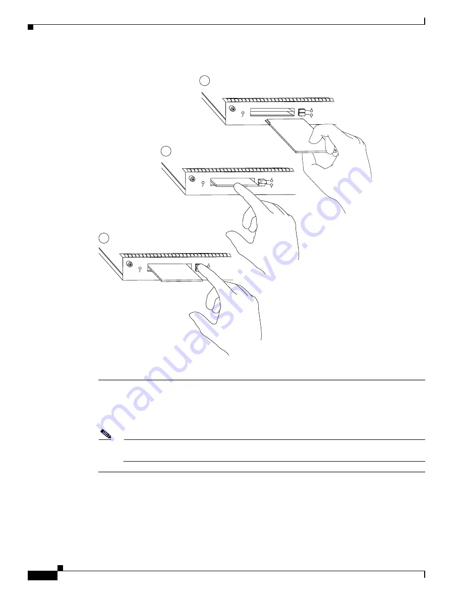
  Installing and Removing a Flash Memory Card

Figure 5-5

Inserting and Removing a Flash Memory Card

Step 1

Orient the Flash memory card so that its connector end faces the appropriate slot. (Refer to 

Figure 5-5

step a.)

Step 2

Carefully guide the card into the slot until the card seats in the slot’s connector and the eject button for 
the slot pops out toward you. (Refer to 

Figure 5-5

, step b.)

Note

Flash memory cards do not insert all the way into the PC Card slots; the end of the card protrudes 
from the I/O controller faceplate. Do not attempt to force the card past this point.

EJE

CT

SLO

T 1

SL

O

T 0

EN

AB

LE

D

a

b

c

EJE

CT

SL

O

T 0

H6437

EJE

CT

SL

O

T 1

EN

AB

LE

D

SLO

T 0

SL

O

T 1

EN

AB

LE

D

Содержание 7206VXR - VPN Bundle Router

Страница 1: ... Systems Inc 170 West Tasman Drive San Jose CA 95134 1706 USA http www cisco com Tel 408 526 4000 800 553 NETS 6387 Fax 408 526 4100 Cisco 7206 Installation and Configuration Guide Customer Order Number Text Part Number OL 5102 02 ...

Страница 2: ...l the interference stops Move the equipment to one side or the other of the television or radio Move the equipment farther away from the television or radio Plug the equipment into an outlet that is on a different circuit from the television or radio That is make certain the equipment and the television or radio are on circuits controlled by different circuit breakers or fuses Modifications to thi...

Страница 3: ...a Service Request xvi Definitions of Service Request Severity xvi Obtaining Additional Publications and Information xvii C H A P T E R 1 Product Overview 1 1 Physical Description 1 2 System Specifications 1 5 Software Requirements 1 6 Field Replaceable Units 1 7 Network Processing Engine 1 7 Input Output Controller 1 14 LED Descriptions 1 18 Port Adapters and Service Adapters 1 24 Power Supplies 1...

Страница 4: ...eral Precautions 2 8 Power Considerations 2 8 Tools for Installation 2 8 Initial Configuration Information 2 9 Cisco 7206 Installation Checklist 2 10 Checking the Shipping Container Contents 2 11 Site Log 2 12 C H A P T E R 3 Installing the Cisco 7206 3 1 Rack Mounting the Cisco 7206 3 2 Attaching the Chassis Rack Mount and Cable Management Brackets 3 5 Installing the Brackets on the Front of the ...

Страница 5: ...6 Configuring the Cisco 7206 Using Configuration Mode 4 9 Saving Your Settings to NVRAM 4 10 Checking Your Settings and Reviewing Your Configuration Changes 4 10 Performing Other Configuration Tasks 4 10 Performing a Complex Configuration 4 11 C H A P T E R 5 Maintaining the Cisco 7206 5 1 Viewing Your System Configuration 5 1 Replacing a Port Adapter or Service Adapter 5 4 Removing a Port or Serv...

Страница 6: ...rocessing Engine 6 7 Troubleshooting the Port Adapter and Service Adapters 6 7 Troubleshooting the Cooling Subsystem 6 7 A P P E N D I X A Industry Standard Wiring Plans 1 A P P E N D I X B Configuration Register Information B 1 Configuration Bit Meanings B 1 Bits 0 3 B 2 Bit 6 B 3 Bit 7 B 3 Bit 8 B 4 Bit 10 and Bit 14 B 4 Bit 11 and Bit 12 B 4 Bit 13 B 4 Bit 15 B 5 Displaying the Configuration Re...

Страница 7: ...o 7206 is installed as a router shelf in a Cisco AS5800 Universal Access Server use this configuration note in conjunction with the Cisco AS5800 Universal Access Server Hardware Installation and Configuration Guide and the Cisco AS5800 Universal Access Server Software Installation and Configuration Guide that shipped with your Cisco AS5800 Universal Access Server Audience To use this publication y...

Страница 8: ...talling the hardware and connecting the external network interface cables Chapter 4 Performing a Basic Configuration of the Cisco 7206 This chapter provides simple procedures for completing a basic system configuration and for checking and saving this configuration to system memory Chapter 5 Maintaining the Cisco 7206 This chapter provides simple maintenance procedures that you might need to perfo...

Страница 9: ...lowing conventions Screen examples use the following conventions Caution Means reader be careful You are capable of doing something that might result in equipment damage or loss of data Note Means reader take note Notes contain helpful suggestions or references to materials not contained in this manual boldface font Commands and keywords are in boldface italic font Arguments for which you supply v...

Страница 10: ...ektrische schakelingen betrokken risico s en dient u op de hoogte te zijn van de standaard praktijken om ongelukken te voorkomen Voor een vertaling van de waarschuwingen die in deze publicatie verschijnen dient u de vertaalde veiligheidswaarschuwingen te raadplegen die bij dit apparaat worden geleverd Opmerking BEWAAR DEZE INSTRUCTIES Opmerking Deze documentatie dient gebruikt te worden in combina...

Страница 11: ...Bevor Sie mit der Arbeit an irgendeinem Gerät beginnen seien Sie sich der mit elektrischen Stromkreisen verbundenen Gefahren und der Standardpraktiken zur Vermeidung von Unfällen bewusst Übersetzungen der in dieser Veröffentlichung enthaltenen Warnhinweise sind im Lieferumfang des Geräts enthalten Hinweis BEWAHREN SIE DIESE SICHERHEITSANWEISUNGEN AUF Hinweis Dieses Handbuch ist zum Gebrauch in Ver...

Страница 12: ...o destina se a ser utilizada em conjunto com o manual de instalação incluído com o produto específico Consulte o manual de instalação o manual de configuração ou outra documentação adicional inclusa para obter mais informações Advertencia INSTRUCCIONES IMPORTANTES DE SEGURIDAD Este símbolo de aviso indica peligro Existe riesgo para su integridad física Antes de manipular cualquier equipo considere...

Страница 13: ...ully understand the content of this user guide you should be familiar with the following terms and acronyms DMA Direct memory access DRAM Dynamic random access memory DCE Data communications equipment DTE Data terminal equipment EPROM Erasable programmable read only memory FRU Field replaceable unit router components that do not require replacement by a Cisco certified service provider ...

Страница 14: ...roduct core 7200vx ol3512 htm for a list of all Cisco 7200 series routers documentation and troubleshooting tools and information Cisco 7200 Series Routers Port Adapter Documentation Roadmap at http www cisco com univercd cc td doc product core 7200vx ol3530 htm for a list of all Cisco 7200 series routers supported port adapter documentation Cisco 7200 Series Routers Troubleshooting Documentation ...

Страница 15: ...sco Systems Corporate Headquarters California USA at 408 526 7208 or elsewhere in North America by calling 800 553 NETS 6387 Documentation Feedback You can send comments about technical documentation to bug doc cisco com You can submit comments by using the response card if present behind the front cover of your document or by writing to the following address Cisco Systems Attn Customer Document O...

Страница 16: ... by telephone S1 or S2 service requests are those in which your production network is down or severely degraded Cisco TAC engineers are assigned immediately to S1 and S2 service requests to help keep your business operations running smoothly To open a service request by telephone use one of the following numbers Asia Pacific 61 2 8446 7411 Australia 1 800 805 227 EMEA 32 2 704 55 55 USA 1 800 553 ...

Страница 17: ... and networking investments Each quarter Packet delivers coverage of the latest industry trends technology breakthroughs and Cisco products and solutions as well as network deployment and troubleshooting tips configuration examples customer case studies certification and training information and links to scores of in depth online resources You can access Packet magazine at this URL http www cisco ...

Страница 18: ...xviii Cisco 7206 Installation and Configuration Guide OL 5102 02 Preface Obtaining Additional Publications and Information ...

Страница 19: ...isco AS5800 Universal Access Server documentation listed in the Preface Related Documentation section on page xiv The Cisco 7206 is part of the Cisco 7200 series routers which consists of the 2 slot Cisco 7202 4 slot Cisco 7204 and Cisco 7204VXR and 6 slot Cisco 7206 and Cisco 7206VXR The Cisco 7206 supports multiprotocol multimedia routing and bridging over a wide variety of LAN and WAN interface...

Страница 20: ...ocal console port for connecting a data terminal or data terminal equipment DTE and an auxiliary port for connecting a modem or other data communications equipment DCE or other devices for configuring and managing the router two PC Card slots for Flash memory cards an optional Fast Ethernet port The Fast Ethernet port provides a 100 Mbps connection to the network Note The I O controller is availab...

Страница 21: ...adapter slot 0 is the Fast Ethernet port on the I O controller refer to Figure 1 2 Note In Figure 1 1 and Figure 1 2 a blank port adapter is installed in slot 5 To ensure adequate airflow across the port adapters each port adapter slot must be filled with either a port adapter or a blank port adapter Figure 1 2 Port Adapter Slot Numbering The rear of the Cisco 7206 router provides access to the ne...

Страница 22: ...lies in the Cisco 7206 In dual power supply router configurations both power supplies must be of the same type two AC input power supplies or two DC input power supplies The power supply has the router s main power switch and either an AC input power receptacle or a hardwired DC input power cable depending on the type of installed power supply Adjacent to the power supply bays are two chassis grou...

Страница 23: ...platform A fully configured Cisco 7206 with two installed power supplies and all chassis slots filled weighs approximately 50 pounds 22 7 kilograms kg For clearance requirements and rack mount installation considerations refer to Chapter 2 Preparing for Installation the Site Requirements section on page 2 2 System Specifications Table 1 1 lists the Cisco 7206 router physical specifications and pow...

Страница 24: ...se of Cisco IOS 12 0 T Note For software information for the Cisco AS5800 Universal Access Server refer to the Cisco AS5800 Universal Access Server documentation listed on Cisco com at http www cisco com univercd cc td doc product access acs_serv as5800 index htm DC voltages supplied and maximum steady state current ratings 5 2V 30A 12 2V 9A 12 0V 1 5A 3 5V 13A DC input cable In accordance with lo...

Страница 25: ...e network processing engine maintains and executes the system management functions for the Cisco 7206 router The network processing engine also shares the system memory and environmental monitoring functions with the I O controller Note Detailed instructions for removing and replacing the network processing engine are contained in the document Network Processing Engine and Network Services Engine ...

Страница 26: ...use DRAM for storing routing tables network accounting applications packets of information in preparation for process switching and packet buffering for SRAM overflow except in the NPE 100 which contains no packet SRAM The standard configuration is 32 MB with up to 128 MB available through single in line memory module SIMM upgrades The NPE 175 and NPE 225 use SDRAM for providing code data and pack...

Страница 27: ...nt through the console and Telnet interface Accounting for and switching of data traffic Booting and reloading images Managing port adapters recognition and initialization during online insertion and removal Figure 1 4 shows the NPE 100 Figure 1 5 shows the NPE 150 Figure 1 6 shows the NPE 175 Figure 1 7 shows the NPE 200 and Figure 1 8 shows the NPE 225 Figure 1 4 NPE 100 H8822 System controller ...

Страница 28: ... sensor Midplane connectors U12 Bank 1 DRAM SIMMs U4 U25 U18 R4700 microprocessor 1 MB SRAM U700 through U703 U800 through U803 Captive installation screw Bank 0 NETWORK PROCESSING ENGINE 150 18077 System controller Midplane connectors Network controller board Boot ROM U1 SDRAM DIMM U15 Handle Captive installation screw RM5270 microprocessor Processor engine board NETWORK PROCESSING ENGINE 150 Tem...

Страница 29: ...ller Temperature sensor Temperature sensor Handle Midplane connectors U52 Bank 1 DRAM SIMMs Boot ROM U92 U42 U25 U11 R5000 microprocessor 4 MB SRAM U6 U10 U13 U14 U28 U29 U38 and U39 Captive installation screw Bank 0 NETWORK PROCESSING ENGINE 200 18078 NETWORK PROCESSING ENGINE 200 System controller Midplane connectors Boot ROM U1 SDRAM DIMM U15 Handle Captive installation screw RM5271 microproces...

Страница 30: ... 100 and the NPE 150 are numbered U18 and U25 The same sockets on the NPE 200 are numbered U11 and U25 2 The sockets for bank 1 on the NPE 100 and the NPE 150 are numbered U4 and U12 The same sockets on the NPE 200 are numbered U42 and U52 SRAM NPE 150 1 MB 8 8 chips each being 128K words x 9 bits wide U700 through U703 U800 through U803 NPE 200 4 MB 8 8 chips each being 512K words x 8 bits wide U...

Страница 31: ...ed external cache U5 U6 U7 U8 1 Located on processor engine board See Figure 1 6 or Figure 1 8 Table 1 3 NPE 175 and NPE 225 Memory Specifications continued Memory Type Size Quantity Description Location1 Table 1 4 DRAM SIMM Configurations NPE 100 NPE 150 and NPE 200 Total DRAM1 1 Refer to the Cisco AS5800 Universal Access Server documentation listed in the Preface Related Documentation section on...

Страница 32: ...is document is available on Cisco com The I O controller is available in these versions C7200 I O FE MII C7200 I O FE The C7200 I O FE MII and C7200 I O FE I O controllers consists of the following components Dual EIA TIA 232 channels for local console and auxiliary ports The console port has full DCE functionality and a DB 25 port The auxiliary port has full DTE functionality and a DB 25 plug An ...

Страница 33: ...nal lithium battery to provide the same functionality as the NVRAM See the second illustration in Figure 1 9 and Figure 1 10 Note Your I O controller with the Fast Ethernet port that has MII and RJ 45 ports C7200 I O FE might look like the first illustration in Figure 1 9 or it might look like the second illustration in Figure 1 9 There is no functional difference between these two I O controllers...

Страница 34: ...M Temperature sensor FPGA configuration PROM U9 PC Card slots Console port Captive installation screw P C M C IA E JE C T S LO T 0 S LO T 1 FE M II FAST ETHERNET INPUT OUTPUT CONTROLLER LEDs CPU reset button 4 MB Flash memory soldered U10 U13 Boot EPROM U4 Auxiliary port R J45 C PU R ESET Optional Fast Ethernet port MII receptacle and RJ 45 receptacle M II E N R J45 E N R J45 LIN K I O P W R O K E...

Страница 35: ...PGA configuration PROM U9 E N A B LE D SRAM U14 Boot EPROM U4 Midplane connectors Battery for SRAM Temperature sensor 4 MB Flash memory soldered U10 U13 C PU R ESET Optional Fast Ethernet port MII receptacle M II E N R J45 LIN K H6000 A U X C O N S O LE Midplane connectors Temperature sensor Flash SIMM U99 NVRAM U41 Temperature sensor Boot ROM U20 PC Card slots Console port Captive installation sc...

Страница 36: ...tem errors and problems use the CPU reset button only at the direction of your service representative Table 1 6 I O Controller Memory Components Memory Type Size Quantity Description Model Location Boot ROM 256 KB 1 32 pin DIP type C7200 I O FE MII U20 32 pin DIP type or 32 pin PLCC type C7200 I O FE C7200 I O U20 or U4 Flash memory 4 MB 1 Contains the default boot helper image C7200 I O FE MII U9...

Страница 37: ...THERNET INPUT OUTPUT CONTROLLER R J 4 5 C PU R ESET M II E N R J45 E N R J45 LIN K IO P W R O K M II E N R J45 E N R J45 LIN K IO P W R O K C P U R E S E T E N A B LE D ENABLED A U X C O N S O LE P C M C IA E JE C T S LO T 0 S LO T 1 FE M II FAST ETHERNET INPUT OUTPUT CONTROLLER R J45 C PU R ESET M II E N R J45 E N R J45 LIN K I O P W R O K 25929 SLOT 1 SLOT 0 M II E N R J45 E N R J45 LIN K I O P ...

Страница 38: ...net Port A U X C O N S O LE P C M C IA E JE C T S LO T 0 C P U R E S E T IO P O W E R O K S LO T 1 INPUT OUTPUT CONTROLLER H7401 S LO T 0 S LO T 1 C P U R E S E T IO P O W E R O K E N A B LE D ENABLED A U X C O N S O LE P C M C IA E JE C T S LO T 0 I O P W R O K S LO T 1 INPUT OUTPUT CONTROLLER 25930 S LO T 0 S LO T 1 C P U R E S E T I O P W R O K E N A B LE D ENABLED C PU R ESET ...

Страница 39: ...d receiving DC power from the router midplane This LED comes on during a successful router boot and remains on during normal operation of the router FE ENABLE Green Indicates that the Fast Ethernet port is initialized and enabled for operation by the system This LED comes on after the I O controller has been enabled and remains on during normal operation of the router FE LINK 1 Green Indicates tha...

Страница 40: ...0 command Note Refer to the Port Adapter Slot and Logical Interface Numbering section on page 1 28 for information about port adapter slot numbering and logical interface numbering for the Cisco 7206 router The following example shows the I O controller with the Fast Ethernet port that is equipped with an MII port and an RJ 45 port Router show diag 0 Slot 0 Fast ethernet on C7200 I O with MII or R...

Страница 41: ...isplay text omitted Encapsulation ARPA loopback not set keepalive not set hdx MII display text omitted Use the media type 100X command to return the media type to the RJ 45 port The default transmission mode for the Fast Ethernet port on the I O controller is half duplex Use the full duplex command to change the Fast Ethernet port s transmission mode and the show interfaces command to verify the c...

Страница 42: ...ce a PA A3 enhanced ATM port adapter in your Cisco 7206 router consult the configuration note PA A3 Enhanced ATM Port Adapter Installation and Configuration The configuration note is available on Cisco com Power Supplies The Cisco 7206 comes equipped with one 280W AC input power supply or one 280W DC input power supply You must order the second power supply separately Caution Do not mix power supp...

Страница 43: ...s the router power supplies a power supply or a power supply filler plate must be installed in each power supply bay Figure 1 3 shows a Cisco 7206 with an installed power supply filler plate Table 1 1 lists the AC input and DC input power supply system power specifications including input voltage and operating frequency ranges Note Each AC input power supply operating at 120 VAC requires a minimum...

Страница 44: ...he power supply remains in a shutdown state until it is disconnected and reconnected to the source power and then restarted with the power switch The power switch turns the power supply on and starts the system For a description of power supply shutdown conditions and thresholds refer to the Environmental Monitoring and Reporting Functions section on page 1 31 Chassis The Cisco 7206 chassis shown ...

Страница 45: ...n boot the router either manually or automatically from any of the stored images Flash memory can also function as a TFTP server to allow other routers to boot remotely from stored images or copy them into their own Flash memory Note For procedures that explain the use of the Flash Disk refer to the Using the Flash Disk document that accompanies every Flash Disk shipped from the factory For proced...

Страница 46: ...pter slot number is the chassis slot in which a port adapter or service adapter is installed whereas the logical interface number is the physical location of the interface port on a port adapter service adapters do not have interface ports Port adapter slots are numbered from 1 through 6 port adapter slot 0 is reserved for the optional Fast Ethernet port on the I O controller if present Refer to F...

Страница 47: ... protocol is up Hardware is DEC21140 address is 0000 0000 0000 bia 0000 0000 0000 Internet address is 10 1 1 3 MTU 1500 bytes BW 100000 Kbit DLY 100 usec rely 255 255 load 1 255 display text omitted Fddi1 0 is administratively down line protocol is down Hardware is MIF68840_MM address is 0000 0000 0000 bia 0000 0000 0000 Internet address is 10 1 1 0 MTU 4470 bytes BW 100000 Kbit DLY 100 usec rely ...

Страница 48: ...han one device at the same time Note Storing the MAC addresses for every slot in one central location means the addresses stay with the memory device on which they are stored Online Insertion and Removal All port adapters and service adapters in the Cisco 7206 support online insertion and removal OIR This function allows you to install and replace port adapters and service adapters while the route...

Страница 49: ...dition within the power supply If conditions reach shutdown thresholds the system shuts down to avoid equipment damage from excessive heat The reporting functions periodically log the values of measured parameters so that you can retrieve them for analysis later and the reporting functions display warnings on the console if any of the monitored parameters exceed defined thresholds Environmental Mo...

Страница 50: ...arameters in NVRAM so you can retrieve it later to help determine the cause of the problem Power supply shutdown The power supply detected an internal out of tolerance overvoltage overcurrent or temperature condition and shut itself down All DC power will remain disabled until you toggle the power switch Note A low warning or high warning message does not mean that the router is at risk of malfunc...

Страница 51: ...g messages on the console if chassis interface monitored parameters exceed a defined threshold You can also retrieve and display environmental status reports with the show environment show environment all show environment last and show environment table commands Parameters are measured and reporting functions are updated every 60 seconds A brief description of each of these commands follows Cautio...

Страница 52: ...ch monitored status level which are related to those thresholds listed in Table 1 10 and Table 1 11 The display also lists the shutdown threshold for the system Following is sample output of the show environment table command for a Cisco 7206 that has an installed NPE 150 Router show environment table Sample Point LowCritical LowWarning HighWarning HighCritical chassis inlet 40C 104F 50C 122F chas...

Страница 53: ... chassis outlet 3 measured at 58C 136F Temperature in Warning range Voltage readings 3 45 V measured at 3 51 V 5 2 V measured at 5 19 V 12 2 V measured at 12 42 V 12 2 V measured at 12 14 V Fan Failures When the system power is on all three fans should be operational The system continues to operate if a fan fails however if the air temperature exceeds a defined threshold the system controller disp...

Страница 54: ...1 36 Cisco 7206 Installation and Configuration Guide OL 5102 02 Chapter 1 Product Overview Functional Overview ...

Страница 55: ...or equipment and site requirements when preparing to install a Cisco 7206 as a router shelf in a Cisco AS5800 Universal Access Server refer to the Cisco AS5800 Universal Access Server documentation listed in the Preface Related Documentation section on page xiv Warning Before your install operate or service the system read the Site Preparation and Safety Guide This guide contains important safety ...

Страница 56: ...lane Site Requirements Use this section for obtaining information about site requirements AC and DC Power The AC input power supply uses a power factor corrector that allows the Cisco 7206 to operate on input voltage and frequency within the ranges of 100 to 240 VAC and 50 to 60 Hz Note We recommend attaching dual power supplies to independent power sources for full redundancy We also recommend an...

Страница 57: ...pacity than twisted pair cabling The distance and rate limits in the following descriptions are the IEEE recommended maximum speeds and distances for signaling however you can usually get good results at speeds and distances far greater than these For example the recommended maximum rate for V 35 is 2 Mbps but it is commonly used at 4 Mbps without any problems If you understand the electrical prob...

Страница 58: ...t after the chassis is installed As an alternative you can mount the Cisco 7206 on an equipment shelf provided that the rack dimensions allow you to secure the router to the shelf and the overall configuration permits safe installation and access However we recommend rack mounting the Cisco 7206 Figure 2 1 shows the Cisco 7206 footprint and outer dimensions To use the rack mounting hardware provid...

Страница 59: ...eight and dimensions of the chassis Figure 2 1 shows the chassis footprint which you will need if you are designing a customized shelf We recommend that you use the rack mount kit designed for the Cisco 7206 Allow sufficient clearance around the rack for maintenance If the rack is mobile you can push it back near a wall or cabinet for normal operation and pull it out for maintenance installing or ...

Страница 60: ...mum of a range indicates a potential problem You can maintain normal operation by anticipating and correcting environmental anomalies before they approach a maximum operating range Preventive Site Configuration Maintaining Normal Operation Planning a proper location for the Cisco 7206 and the layout of your equipment rack or wiring closet are essential for successful system operation Equipment pla...

Страница 61: ... the internal air temperature and send warning messages when the internal air temperature approaches a specified threshold If the internal temperature exceeds the specified threshold the system environmental monitor shuts down all internal power to prevent equipment damage from excessive heat See Chapter 1 Product Overview the Environmental Monitoring and Reporting Functions section on page 1 31 f...

Страница 62: ...the power at your site before installation and periodically after installation to ensure that you are receiving clean power Install a power conditioner if necessary Install proper grounding to avoid damage from lightning and power surges Note The Cisco 7206 installation must comply with all applicable codes and is approved for use with copper conductors only The ground bond fastening hardware shou...

Страница 63: ...or EIA 530 electrical interface Ethernet transceiver Token Ring multistation access unit MSAU Optical bypass switch or concentrator for multimode Fiber Distributed Data Interface FDDI connections Initial Configuration Information After you install the chassis and verify that all the hardware is operating properly you must configure the system and individual interfaces before you can connect your s...

Страница 64: ...idelines reviewed Installation Checklist copied Site log established and background information entered Site power voltages verified Site environmental specifications verified Required passwords IP addresses device names and so on available Required tools available Network connection equipment available Router mounted in rack optional Cable management brackets installed optional but recommended AC...

Страница 65: ...heck the contents of the accessories box against the Cisco 7206 Component List and the packing slip to verify that you received all listed equipment which should include the following One modular power cable for each AC input power supply One rack mount and cable management kit four brackets and 14 mounting screws Optional equipment that you ordered such as network interface cables transceivers or...

Страница 66: ...wer supply removed or replaced Chassis replaced Configuration changed port or service adapters moved Software upgraded Corrective maintenance procedures performed Intermittent problems Related comments Table 2 4 shows a sample site log page Make copies of the sample or design your own site log to meet the needs of your site and equipment Table 2 3 Cisco 7206 Component List Component Description Re...

Страница 67: ...2 13 Cisco 7206 Installation and Configuration Guide OL 5102 02 Chapter 2 Preparing for Installation Site Log Table 2 4 Site Log Example Date Description of Action Performed or Symptom Observed Initials ...

Страница 68: ...2 14 Cisco 7206 Installation and Configuration Guide OL 5102 02 Chapter 2 Preparing for Installation Site Log ...

Страница 69: ...intained by service personnel as defined by AS NZS 3260 Incorrect connection of this or connected equipment to a General Purpose Outlet could result in a hazardous situation The telecommunications lines must be disconnected before unplugging the main power connection and while the housing is open A rack mount and cable management kit is included in the shipping container The rack mount brackets in...

Страница 70: ...g fastener points and ensure that you will be able to pull port adapters and other FRUs straight out of their respective slots The inlet and exhaust ports for cooling air are located on the right and left of the chassis respectively so multiple routers can be stacked in a rack with little or no vertical clearance Figure 3 1 Typical Four Post Equipment Rack Posts and Mounting Strips If you want the...

Страница 71: ... M II LI N K R J4 5 FAST ETHERNET 0 3 5 1 2 0 H9445 Rack mount bracket M II E N R J4 5 E N R J4 5 LI N K 1O P W R O K RJ 4 5 CP U RE SE T FAST ETHERNET INPUT OUTPUT CONTROLLER E N A B L E D P C M C IA E JE C T S L O T 0 S L O T 1 F E M II H9446 Rack mount bracket 4 6 FAST SERIAL EN TD TC RD RC LB CD TD TC RD RC LB CD TD TC RD RC LB CD TD TC RD RC LB CD ETHERNET 10BFL E N R X 0 1 2 3 4 T X R X T X ...

Страница 72: ...In the second configuration two screws secure each rack mount bracket to the chassis and two additional screws secure each cable management bracket to a rack mount bracket Refer to Figure 3 5 Figure 3 4 Rack Mounting the Chassis in a Telco Type Rack with Installed Cable Management Brackets Front Installation Shown H9453 4 6 FAST SERIAL EN TD TC RD RC LB CD TD TC RD RC LB CD TD TC RD RC LB CD TD TC...

Страница 73: ...from the front and you plan to use the cable management brackets you must install the cable management brackets when you install the rack mount brackets on the chassis If you are rack mounting the chassis from the rear you may install the rack mount and cable management brackets separately however both sets of brackets must be installed on the chassis before the chassis is installed in the rack Th...

Страница 74: ...ment bracket to the threaded holes in the right side of the chassis as shown in Figure 3 6 If you want the front of the chassis recessed in the rack align the first rack mount bracket to the threaded holes in the right side of the chassis as shown in Figure 3 7 Figure 3 6 Installing the Rack Mount Brackets on the Front of the Chassis so the Front Protrudes from the Rack 4 6 FAST SERIAL EN TD TC RD...

Страница 75: ...ed and rack mount bracket This completes the procedure for installing the rack mount and cable management brackets on a Cisco 7206 for a front rack mount configuration Installing Brackets on the Rear of the Chassis To install the rack mount and cable management brackets on a Cisco 7206 for a rear rack mount configuration complete the following steps Step 1 Locate the threaded holes in the rear sid...

Страница 76: ...ips screwdriver to tighten the screws Step 7 Repeat Step 5 and Step 6 for the other cable management brackets 2 4 FAST SERIAL EN TD TC RD RC LB CD TD TC RD RC LB CD TD TC RD RC LB CD TD TC RD RC LB CD ETHERNET 10BFL E N R X 2 3 4 T X R X T X R X T X R X T X R X T X TOKEN RING 0 1 2 3 ETHERNET 10BT EN AB LE D 0 2 1 3 LIN K 0 1 2 3 EN A B LE D M II LI N K R J4 5 FAST ETHERNET 0 1 3 1 2 Cisco 7200 Se...

Страница 77: ...erwise stabilized Note Two people should perform Step 3 through Step 6 Step 3 Position the chassis so that the front end is closest to you Lift the chassis and move it to the rack To prevent injury avoid sudden twists or moves Step 4 Slide the chassis into the rack pushing it back until the brackets installed at the front or rear of the chassis meet the mounting strips or posts on both sides of th...

Страница 78: ... Step 1 Remove any debris and dust from the tabletop or workbench as well as the surrounding area Also make sure your path between the router and its new location is unobstructed Step 2 On the chassis ensure that all captive screws on the network processing engine the I O controller and each power supply are tightened and the port adapter levers are in the locked position Step 3 Lift the chassis b...

Страница 79: ...erface cable before securing it to the cable management bracket Step 3 With the interface cables between the ends of the tie wrap and the interface cables service loop in place tighten the cable tie down around the interface cables until they are secured against the cable management bracket Refer to Figure 3 10 Figure 3 10 Securing Interface Cables to the Cable Management Brackets Step 4 Repeat St...

Страница 80: ...ng between them and a wire receptacle large enough to accept a 6 AWG multistrand copper wire See Figure 3 12 This grounding lug is not available from Cisco Systems electrical connector vendors provide this type of grounding lug Two Phillips head machine screws with locking washers M5 metric 0 031 inch 0 8 mm pitch 0 315 inch 8 mm length These screws are not available from Cisco Systems they are av...

Страница 81: ...unding Lug to the Chassis Grounding Receptacles Step 3 Use the Phillips screwdriver to carefully tighten the screws until the grounding lug is held firmly to the chassis Do not overtighten the screws Step 4 Use the wire stripper to strip one end of the 6 AWG wire approximately 0 75 inches 19 05 mm Step 5 Insert the 6 AWG wire into the wire receptacle on the grounding lug See Figure 3 12 Step 6 Use...

Страница 82: ...ins connection equipment and pinout information for the console auxiliary and Fast Ethernet ports on the I O controller Figure 3 13 Cisco 7206 I O Controller Connections Console and Auxiliary Port Connection Equipment The I O controller has two EIA TIA 232 ports a DCE mode console port and a DTE mode auxiliary port Refer to Figure 3 14 The console port is a DCE DB 25 connector for connecting a dat...

Страница 83: ...the terminal You must supply your own interface cable between the auxiliary port and the equipment you are connecting For console and auxiliary port pinouts refer to the following sections Console Port Signals and Auxiliary Port Signals Figure 3 14 Console and Auxiliary Port Connections Console Port Signals Table 3 1 lists the signals used on the console port The console port does not support mode...

Страница 84: ...rted by Cisco Systems the I O controller equipped with the single MII port was discontinued as an orderable product in May 1998 The following sections explain Fast Ethernet MII and RJ 45 connection equipment Table 3 1 Console Port Signals Pin Signal Direction Description 1 GND Ground 2 TxD Transmit Data 3 RxD Receive Data 6 DSR Data Set Ready always on 7 GND Ground 8 DCD Data Carrier Detect always...

Страница 85: ...your 100BASET transceiver should be appropriately equipped with ST type connectors for optical fiber BNC connectors and so forth Figure 3 16 shows the pin orientation of the MII port on the I O controller The MII port uses two 56 screw type locks called jackscrews to secure the cable or transceiver to the port MII cables and transceivers have knurled thumbscrews that you fasten to the jackscrews o...

Страница 86: ... not supply Category 5 UTP cables these cables are available commercially Figure 3 17 shows the RJ 45 port and connector Table 3 4 lists the pinouts and signals for the RJ 45 port Figure 3 17 RJ 45 Port and Plug Table 3 3 MII Port Pinout Pin1 1 Any pins not indicated are not used In Out I O Description 14 17 Yes Transmit Data TxD 12 Yes Transmit Clock Tx_CLK 2 2 Tx_CLK and Rx_CLK are provided by t...

Страница 87: ... Figure 3 19 for straight through and crossover twisted pair cable connections Figure 3 18 Straight Through Cable Pinout I O Controller RJ 45 Connection to an End Station or DTE Figure 3 19 Crossover Cable Pinout I O Controller RJ 45 Connection to an End Station or DTE To identify the RJ 45 cable type hold the two ends of the cable next to each other so you can see the colored wires inside the end...

Страница 88: ...ains important safety information you should know before working with the system This section provides the procedures for connecting AC input and DC input power to your Cisco 7206 Warning This unit might have more than one power cord To reduce the risk of electric shock disconnect the two power supply cords before servicing the unit Note Detailed instructions for handling and replacing the Cisco 7...

Страница 89: ...or the Cisco 7206 has double pole neutral fusing Figure 3 21 Connecting AC Input Power Step 4 Plug the AC power supply cable into the AC power source Step 5 Repeat Step 1 through Step 4 for the second power supply if present This completes the procedure for connecting AC input power Connecting DC Input Power Connect a 280W DC input power supply as follows Note The color coding of the DC input powe...

Страница 90: ... that no current is flowing through the DC power supply leads To ensure that all power is OFF locate the circuit breaker on the panel board that services the DC circuit switch the circuit breaker to the OFF position and tape the switch handle of the circuit breaker in the OFF position Step 2 Using a wire stripper strip approximately 0 55 inch 14 mm from the V V and ground leads refer to Figure 3 2...

Страница 91: ...o the power supply faceplate leave a small service loop in the ground lead to ensure that the ground lead is the last lead to disconnect from the power supply if a great deal of strain is placed on all three leads refer to Figure 3 23 Step 7 Switch the circuit breaker to the ON position Note Each DC input power supply operating at 24 VDC requires a minimum of 19A service Each DC input power supply...

Страница 92: ... Observe the initialization process When the system boot is complete a few seconds the network processing engine begins to initialize the port adapters and the I O controller During this initialization the LEDs on each port adapter behave differently most flash on and off The enabled LED on each port adapter goes on when initialization is completed and the console screen displays a script and syst...

Страница 93: ...ete the first time startup procedures and configuration and then refer to the configuration note for each port adapter for LED descriptions and to check the status of the interfaces If the system does not complete each of the steps in the startup procedure proceed to Chapter 6 Troubleshooting the Installation for troubleshooting recommendations and procedures Your installation is complete Proceed ...

Страница 94: ...3 26 Cisco 7206 Installation and Configuration Guide OL 5102 02 Chapter 3 Installing the Cisco 7206 Starting the Cisco 7206 ...

Страница 95: ...ope of this publication and can be found in the configuration publications listed in the Preface Related Documentation section on page xiv To configure the Cisco 7206 from a console you need to connect a terminal to the router s console port Configuration requires access to the console port on the router s I O controller Using the Enable Secret and the Enable Password The Cisco 7206 is administere...

Страница 96: ...g the configuration process check the current state of the router by entering the show version command The show version command displays the release of Cisco IOS software that is available on the router Configuring the Cisco 7206 Using AutoInstall The AutoInstall process is designed to configure the Cisco 7206 automatically after connection to your WAN For AutoInstall to work properly a Transmissi...

Страница 97: ...onfigured it defaults to the setup facility If the serial WAN cable is not connected the router boots from Flash memory and go automatically into the setup facility Note You can run the setup facility any time you are at the enable prompt by entering the command setup Configuring Global Parameters When you first start the setup program you must configure the global parameters These parameters are ...

Страница 98: ...alled hardware appear only at initial system startup On subsequent uses of the setup command facility the script begins with a System Configuration Dialog as shown in the following example System Configuration Dialog At any point you may enter a questions mark for help Use ctrl c to abort configuration dialof at any prompt Default settings are in square brackets continue with configuration dialog ...

Страница 99: ... Configure SNMP Network Management yes Community string public Step 6 For the following query do not enable CLNS Configure CLNS no Step 7 For the following queries enable routing on AppleTalk and IPX Configure AppleTalk no yes Multizone networks no yes Configure IPX no yes Step 8 For the following queries do not enable Vines XNS DECnet or bridging Configure Vines no Configure XNS no Configure DECn...

Страница 100: ...e IPX no y Configure AppleTalk no y Multizone networks no y Configure Apollo no Configure DECnet no Configure XNS no Configure CLNS no Configure bridging no Step 10 Save your settings to NVRAM Refer to the Saving Your Settings to NVRAM section on page 4 10 Configuring Interfaces Following are the steps for configuring interfaces to allow communication over a LAN or WAN To configure the interface p...

Страница 101: ...s well Configuring Synchronous Serial Interfaces Synchronous serial interfaces are configured to allow connection to WANs through a CSU DSU Complete the following steps to configure the serial ports Step 1 To configure serial port 0 enter yes Configuring interface Serial1 0 Is this interface in use no yes Step 2 Determine which protocols you want on the synchronous serial interface and enter the a...

Страница 102: ...work no yes AppleTalk starting cable range 0 Configuring interface Serial1 0 Is this interface in use no yes Configure IP on this interface no yes Configure IP unnumbered on this interface no IP address for this interface 10 1 1 20 Number of bits in subnet field 0 Class A network is 1 0 0 0 0 subnet bits mask is 255 0 0 0 Configure IPX on this interface no yes IPX network number 2 Configure AppleT...

Страница 103: ...o configure the Cisco 7206 manually Step 1 Connect a console terminal to the console port on the I O controller Step 2 When asked if you want to enter the initial dialog answer no to go into the normal operating mode of the router Would you like to enter the initial dialog yes no Step 3 After a few seconds the user EXEC prompt Router is displayed Type enable to enter enable mode configuration chan...

Страница 104: ... the router Checking Your Settings and Reviewing Your Configuration Changes You can check your settings and review any changes to your configuration by using various software commands To check the value of the settings you have entered enter the show running config command at the Router prompt Router show running config To review changes you make to the configuration use the EXEC show startup conf...

Страница 105: ...nstalled the Cisco 7206 hardware checked all external connections turned on the system power allowed the system to boot up and minimally configured the system you might need to perform more complex configurations which are beyond the scope of this publication For specific information on system and interface configuration refer to the publications listed in the Preface Related Documentation section...

Страница 106: ...4 12 Cisco 7206 Installation and Configuration Guide OL 5102 02 Chapter 4 Performing a Basic Configuration of the Cisco 7206 Performing a Complex Configuration ...

Страница 107: ...eplace main Flash and ROM monitor memory in Cisco 7200 series routers refer to the Memory Replacement Instructions for the Network Processing Engine or Network Services Engine and Input Output Controller document The preceding documents are available on Cisco com Viewing Your System Configuration You can use the show version and the show diag commands to view information specific to the hardware c...

Страница 108: ...ister is 0x0 Use the show diag command to determine what type of port adapters and I O controller with or without the Fast Ethernet port are installed in slot 0 through slot 6 of your Cisco 7206 You can also use the show diag slot command to display information about a specific port adapter slot The following example shows the output from the show diag command The I O controller listed in slot 0 h...

Страница 109: ...ion A0 Serial number 4294967295 Part number 73 1556 04 Test history 0x0 RMA number 00 00 00 EEPROM format version 1 EEPROM contents hex 0x20 01 02 01 01 FF FF FF FF 49 06 14 04 00 00 00 00 0x30 50 00 00 00 FF FF FF FF FF FF FF FF FF FF FF FF Slot 5 Compression engine 768K port adapter 0 ports Port adapter is analyzed Port adapter insertion time 00 11 11 ago Hardware revision 255 255 Board revision...

Страница 110: ...nished chassis surface Warning During this procedure wear grounding wrist straps to avoid ESD damage to the card Do not directly touch the backplane with your hand or any metal tool or you could shock yourself Step 2 Place the port adapter lever for the desired port adapter slot in the unlocked position The lever remains in the unlocked position Refer to Figure 5 1 Figure 5 1 Placing the Port Adap...

Страница 111: ...or pins Refer to Figure 5 2 Figure 5 2 Port and Service Adapter Handling Side View Step 6 Place the adapter on an antistatic surface with its components facing upward or in a static shielding bag If the adapter will be returned to the factory immediately place it in a static shielding bag This completes the procedure for removing a port or service adapter from the Cisco 7206 router Installing a Po...

Страница 112: ...ort adapter half way in the slot connect all required cables to the port adapter Note For connection equipment signaling and pinout information for a specific port adapter type refer to the configuration note for the port adapter For example connection equipment signaling and pinout information for the Fast Ethernet port adapter is contained in the configuration note PA FE TX and PA FE FX Fast Eth...

Страница 113: ...y Card Complete the following steps to insert a Flash memory card in either PC Card slot Note To avoid potential problems when inserting spare Flash memory cards in your Cisco 7206 we recommend that you reformat all of your Flash memory cards on a Cisco 7206 running one of the recommended Cisco IOS software releases The Reformatting a Flash Memory Card section on page 5 12 contains instructions th...

Страница 114: ...lot Refer to Figure 5 5 step a Step 2 Carefully guide the card into the slot until the card seats in the slot s connector and the eject button for the slot pops out toward you Refer to Figure 5 5 step b Note Flash memory cards do not insert all the way into the PC Card slots the end of the card protrudes from the I O controller faceplate Do not attempt to force the card past this point EJECT SLOT ...

Страница 115: ... reformat all of your Flash memory cards on a Cisco 7206 running one of the recommended Cisco IOS software releases The Reformatting a Flash Memory Card section on page 5 12 contains instructions that explain how to reformat a Flash memory card Caution The following formatting procedure erases all information on the Flash memory card To prevent the loss of important data that might be stored on a ...

Страница 116: ...he setup command facility For instructions on using this procedure refer to Chapter 4 Performing a Basic Configuration of the Cisco 7206 the Configuring the Cisco 7206 Manually Using the Setup Facility section on page 4 3 You know the filename of the image you want you want to copy onto the Flash memory card Following is the procedure for copying a bootable file called new image in the examples on...

Страница 117: ...erminal Router config no boot system Router config boot system flash slot0 new image Router config z Router copy running config startup config Router reload When the system reloads it will boot the new image file from the Flash memory card This completes the procedure for copying a bootable image onto a Flash memory card Copying Bootable Images between Flash Memory Cards As future releases of Cisc...

Страница 118: ...Step 3 Insert the new Flash memory card in slot 1 Step 4 Use the following command to copy the file new image in slot 1 to the Flash memory card in slot 0 only if there is enough memory space for the two images to coexist If there is not enough memory space proceed to Step 5 Router copy slot1 new image slot0 new image Note You can also enter the preceding command as copy slot1 new image slot0 Step...

Страница 119: ...procedure refer to Chapter 4 Performing a Basic Configuration of the Cisco 7206 the Configuring Interfaces section on page 4 6 You know the filename of the image you want you want to copy to the TFTP server or onto the secondary Flash memory card Use the following procedure to reformat a Flash memory card Step 1 Insert the Flash memory card into slot 0 If slot 0 is not available use slot 1 Refer t...

Страница 120: ...t password is encrypted however and must be replaced with a new enable secret password Overview of the Password Recovery Procedure Following is an overview of the steps in the password recovery procedure Step 1 If you can log in to the router enter the show version command to determine the existing configuration register value Step 2 Press the Break key to get to the bootstrap program prompt ROM m...

Страница 121: ...Proceed to Step 6 If Break is disabled power cycle the router turn the router off or unplug the power cord and then restore power Then proceed to Step 5 Step 5 Within 60 seconds of restoring the power to the router press the Break key or send a Break This action causes the router to enter the ROM monitor and display the ROM monitor prompt rommon1 Step 6 Set the configuration register using the con...

Страница 122: ...mory This action allows you to modify or replace passwords in the configuration Router configure memory Step 13 Enter the privileged EXEC command configure terminal to enter configuration mode Hostname configure terminal Step 14 Change all three passwords using the following commands Hostname config enable secret newpassword1 Hostname config enable password newpassword2 Hostname config line con 0 ...

Страница 123: ...12 through Step 15 skip to Step 19 Failure to observe this caution will cause you to erase your router configuration file Step 18 Enter the copy running config startup config command to save the new configuration to NVRAM Step 19 Enter the reload command to reboot the router Step 20 Log in to the router with the new or recovered passwords This completes the steps for recovering or replacing a lost...

Страница 124: ...5 18 Cisco 7206 Installation and Configuration Guide OL 5102 02 Chapter 5 Maintaining the Cisco 7206 Replacing or Recovering a Lost Password ...

Страница 125: ...y default settings the recommendations in this chapter might not apply Make sure to review the safety warnings listed in the publication Regulatory Compliance and Safety Information for the Cisco 7200 Series Routers that accompanied your Cisco 7206 before using the troubleshooting procedures in this chapter Contacting a Customer Service Representative If you are unable to easily solve the problem ...

Страница 126: ...blem solving Turn on system power Troubleshoot power subsystem Troubleshoot cooling subsystem Reseat I O controller and restart Reseat NPE G1 and restart System startup successful Reseat port adapters and restart Obtain technical assistance DC OK LED on Fans operating Fans operating I O controller LEDs OK Port adapter enabled LEDs on H6595 Yes No Yes Yes Yes Yes No No No No Yes Yes Yes Check syste...

Страница 127: ... I O controller or port or service adapter that is dislodged from the midplane Although an overtemperature condition is unlikely at initial startup the environmental monitoring functions are included in this chapter because they also monitor internal voltages When you start up the Cisco 7206 for the first time you should observe the startup sequence described in Chapter 3 Installing the Cisco 7206...

Страница 128: ...ontroller section on page 6 6 Note The I O controller without the Fast Ethernet port does not have the FE ENABLE LED and the FE LINK LED The I O controller without the Fast Ethernet port and the I O controller that is equipped with a single MII port do not have the MII EN RJ 45 EN and RJ 45 LINK LEDs The FE LINK LED comes on only when the Fast Ethernet port on the I O controller is receiving a car...

Страница 129: ... to the Troubleshooting the Port Adapter and Service Adapters section on page 6 7 When all LEDs come on to indicate that the system has booted successfully the initial system banner should be displayed on the console screen If it is not displayed refer to the Console and Auxiliary Port Connection Equipment section on page 3 14 in Chapter 3 Installing the Cisco 7206 to verify that the terminal is s...

Страница 130: ...I O controller and the network processing engine are installed properly and the system software has initialized successfully Then if necessary you can troubleshoot individual port and service adapters Troubleshooting the I O Controller The procedures in this section assume that the I O controller network processing engine and router itself are in the original factory configuration and that you hav...

Страница 131: ...the enabled LED remains off the system detected a processor hardware failure This LED should be on in normal operation Contact a service representative for instructions Troubleshooting the Cooling Subsystem Check the following to help isolate a problem with the cooling system When you start up the system do the fans start operating To determine if the fans are operating listen for them In noisy en...

Страница 132: ...the system shuts down use the show environment or show environment table command to display the internal chassis environment Refer to the Functional Overview section in Chapter 1 Product Overview for descriptions of the show environment and show environment table commands If you experience trouble with the startup that is not resolved with these procedures contact a service representative for assi...

Страница 133: ...a binder group of 25 pairs The colors used for a group are white red black yellow and violet The colors used for pair within group are blue orange green brown and slate Each pair must have a unique color combination One wire within each pair has a solid background of its group color and stripes of the pair within group color the second wire has the colors reversed Table A 1 lists the sequences Not...

Страница 134: ... Green Black 13 14 1 Black Brown 39 14 2 Brown Black 14 15 1 Black Slate 40 15 2 Slate Black 15 16 1 Yellow Blue 41 16 2 Blue Yellow 16 17 1 Yellow Orange 42 17 2 Orange Yellow 17 18 1 Yellow Green 43 18 2 Green Yellow 18 19 1 Yellow Brown 44 19 2 Brown Yellow 19 20 1 Yellow Slate 45 20 2 Slate Yellow 20 21 1 Violet Blue 46 21 2 Blue Violet 21 22 1 Violet Orange 47 22 2 Orange Violet 22 23 1 Viole...

Страница 135: ...wire color code The alternate color code is included because sometimes the station wire uses the first three pairs of the standard color code white blue blue white and so on while other times it uses the six alternate colored wires Table A 2 Second Color Code Scheme for Smaller Numbers of Wires Pair Number Wire Number Solid Color Stripe Color Alternate Color Pin Number 1 1 White Blue Green 4 1 2 B...

Страница 136: ...A 4 Cisco 7206 Installation and Configuration Guide OL 5102 02 Appendix A Industry Standard Wiring Plans ...

Страница 137: ... the following Set and display the configuration register value Force the system into the bootstrap program Select a boot source and default boot filename Enable or disable the Break function Control broadcast addresses Set the console terminal baud rate Load operating software from ROM Enable booting from a Trivial File Transfer Protocol TFTP server Table B 1 lists the meaning of each of the conf...

Страница 138: ...or netbooting If there are no boot commands in the configuration file the router attempts to boot the first file in system Flash memory If no file is found in system Flash memory the router attempts to netboot a default file with a name derived from the value of the boot field for example cisco2 7200 If the netboot attempt fails the boot helper image in boot flash memory will boot up If boot comma...

Страница 139: ... name Table B 3 lists the default boot filenames or actions Note A boot system configuration command in the router configuration in NVRAM overrides the default netboot filename Bit 6 Bit 6 causes the system software to ignore nonvolatile random access memory NVRAM contents Bit 7 Bit 7 enables the OEM bit It disables the bootstrap messages at startup Table B 3 Default Boot Filenames Action File Nam...

Страница 140: ...14 Bit 11 and Bit 12 Bit 11 and Bit 12 in the configuration register determine the baud rate of the console terminal Table B 5 shows the bit settings for the four available baud rates The factory set default baud rate is 9600 Bit 13 Bit 13 determines the server response to a bootload failure If boot commands are in the configuration file the router software processes each boot command in sequence ...

Страница 141: ... slot0 cisco 7206 NPE150 processor with 12288K 4096K bytes of memory R4700 processor Implementation 33 Revision 1 0 Level 2 Cache Last reset from power on Bridging software X 25 software Version 2 0 NET2 BFE and GOSIP compliant Basic Rate ISDN software version 1 0 Chassis Interface 12 Ethernet IEEE 802 3 interfaces 1 FastEthernet IEEE 802 3 interface 4 ISDN Basic Rate interfaces 1 Compression port...

Страница 142: ...o IOS The configuration register can be set in the configuration mode with the config register 0x value command See the following sample output Router config t Enter configuration commands one per line End with CNTRL Z Router config config register 0x2142 Router config end Router SYS 5 CONFIG_I Configured from console by console Setting the Configuration Register While Running ROM Monitor If the p...

Страница 143: ...gnore system config info y n n n change console baud rate y n n n change the boot characteristics y n n y enter to boot 0 ROM Monitor 1 the boot helper image 2 15 boot system 0 2 Configuration Summary enabled are load rom after netboot fails console baud 9600 boot image sepcified by the boot system commands or default to cisco2 c7200 do you wish to change the configuration y n n n You must reset o...

Страница 144: ... A L P H A D R A F T C I S CO CO N F I D E N T I A L B 8 Cisco 7206 Installation and Configuration Guide OL 5102 02 Appendix B Configuration Register Information Setting the Configuration Register While Running ROM Monitor ...

Страница 145: ...ptive installation screws 2 1 changes reviewing configuration 4 10 chassis clearance 1 33 footprint 2 5 ground receptacles 1 4 lifting 3 9 physical description 1 26 rack mounting 3 2 checklist installation 2 10 Cisco IOS requirements 1 6 clearance chassis 1 33 commands boot system flash 5 12 config terminal 4 9 configure 4 9 copy 5 10 5 12 copy running config startup config 4 3 4 10 enable 4 9 ena...

Страница 146: ...onsole and auxiliary 3 14 console port signals 3 15 Fast Ethernet MII and RJ 45 on I O controller 3 16 connector auxiliary port 3 16 console port 3 15 console terminal system banner display 6 5 cooling subsystem 6 3 6 7 copy command 5 10 copy command Flash memory 5 12 copy running config startup config command 4 3 4 10 critical status level environmental monitor 1 32 crossover cable RJ 45 receptac...

Страница 147: ...sh memory card 5 7 memory options 1 27 physical description 1 27 Flash memory disk memory options 1 28 physical description 1 27 FRUs listing 1 7 G global parameters configuring 4 3 ground receptacles chassis 1 4 H handles I O controller 1 2 network processing engine 1 4 port adapter 1 3 5 5 power supply 1 24 hardware address 1 28 I I O controller handling 2 2 LEDs 6 3 MII receptacle 3 17 normal s...

Страница 148: ...or troubleshooting 6 7 system management functions 1 9 nonvolatile random access memory See NVRAM 4 10 normal status level environmental monitor 1 32 1 33 note description ix numbering logical interface 1 28 port adapter slot 1 28 NVRAM log 1 32 saving and viewing contents 4 10 See nonvolatile random access memory O OIR functional description 1 30 operating conditions for chassis 1 25 2 2 out of t...

Страница 149: ...g the chassis 3 12 installing and removing a Flash memory card 5 7 installing brackets on the chassis 3 5 installing chassis on a tabletop general installation 3 9 rack mounting chassis 3 2 replacing a port adapter 5 4 replacing a service adapter 5 4 replacing or recovering a lost password 5 14 starting the Cisco 7206 3 24 viewing your system configuration 5 1 processor shutdown 1 32 system for tr...

Страница 150: ...ntive configuration 2 6 slot port numbers for interfaces 1 28 SNMP 4 5 SNMP management 1 9 software requirements 1 6 startup system 3 24 status DC power 1 32 environmental 1 33 2 8 interfaces 1 29 straight through cable RJ 45 receptacle on I O controller 3 19 subsystems for troubleshooting cooling 6 7 I O controller 6 6 network processing engine 6 7 port adapters 6 7 power 6 5 service adapters 6 7...

Отзывы: