


© Copyright 2007 Cisco Systems, Inc.
This document may be freely reproduced and distributed whole and intact including this Copyright Notice.
7
Auxiliary Power Off
Solid Green
Solid Orange
-48V PS and RPS not present
-48V PS or RPS present and functional
-48V PS or RPS present and failure detected
Activity
Off
Blinking Green
Solid Green
No interrupts or packet transfer occurring
System is servicing interrupts
System is actively transferring packets
Compact Flash
Off
Solid Green
No ongoing accesses, eject permitted
Device is busy, do not eject
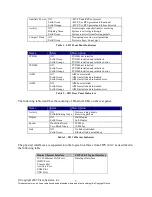
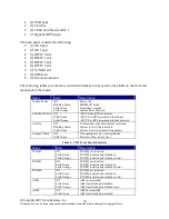
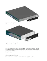
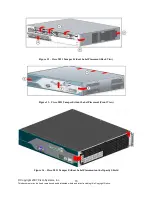
Table 1 – 2811 Front Panel Indicators
Name
State
Description
PVDM1
Off
Solid Green
Solid Orange
PVDM1 not installed
PVDM1 installed and initialized
PVDM1 installed and initialized error
PVDM0
Off
Solid Green
Solid Orange
PVDM0 not installed
PVDM0 installed and initialized
PVDM0 installed and initialized error
AIM1
Off
Solid Green
Solid Orange
AIM1 not installed
AIM1 installed and initialized
AIM1 installed and initialized error
AIM0
Off
Solid Green
Solid Orange
AIM0 not installed
AIM0 installed and initialized
AIM0 installed and initialized error
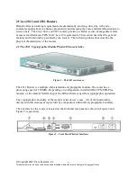
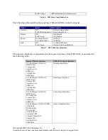
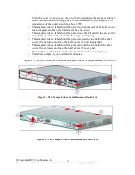
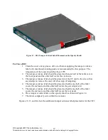
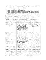
Table 2 – 2811 Rear Panel Indicators
The following table describes the meaning of Ethernet LEDs on the rear panel:
Name
State
Description
Activity
Off
Solid/Blinking Green
Not receiving packets
Receiving packets
Duplex
Off
Solid Green
Half-Duplex
Full-Duplex
Speed
One Blink Green
Two Blink Green
10 Mbps
100 Mbps
Link
Off
Solid Green
No link established
Ethernet link is established
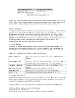
Table 3 – 2811 Ethernet Indicators
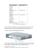
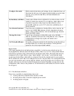
The physical interfaces are separated into the logical interfaces from FIPS 140-2 as described in
the following table:
Router Physical Interface
FIPS 140-2 Logical Interface
10/100 Ethernet LAN Ports
HWIC Ports
Console Port
Auxiliary Port
ENM Slot
USB Ports
Data Input Interface