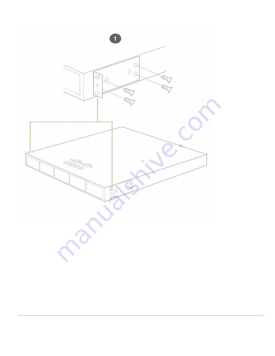
2. Align the rack mount brackets on the sides of the switch onto the rack.
10
Страница 1: ...ble fans MS390 24U HW Stackable Layer 3 24 port Gbe UPOE switch with 10G 40G modular uplinks hot swappable power supplies and hot swappable fans MS390 24UX HW Stackable Layer 3 24 port mGbe UPOE switc...
Страница 2: ...90 Model Interfaces PoE UPoE Capabilities Power Load idle max Available PoE Hot Swap Power Supply MS390 24 HW 24 x 1GbE RJ45 n a 79 2 99 W Yes Dual MS390 24P HW 24 x 1GbE RJ45 PoE 84 1 554 4 W 445W Ye...
Страница 3: ...the inital stage of boot up process Cycling through different colors Management plane is initializing and the switch initiates communication to Meraki cloud Solid white Switch is fully operational and...
Страница 4: ...local status page 2 Stack Ports N A Stack Cables are connected here 3 Redundant Fans Green Active and operational 4 StackPower Ports N A StackPower cables are connected here 5 Power Supplies Green Act...
Страница 5: ...0 24U Series front panel MS390 24UX Series front panel MS390 48 Series front panel MS390 48P Series front panel MS390 48U Series front panel MS390 48UX Series front panel MS390 48UX2 Series front pane...
Страница 6: ...utton If the button is pressed and held for at least 10 to 15 seconds and then released the switch will reboot and be restored to its original factory settings by deleting all configuration informatio...
Страница 7: ...e hazards involved with electrical circuitry and be familiar with standard practices for preventing accidents Read the mounting instructions carefully before beginning installation Failure to use the...
Страница 8: ...by default however the active VLANs can be changed via the local status page or dashboard When installing an MS390 it is important to ensure that any DHCP services or IP address assignments used for...
Страница 9: ...t may take some time for a device to boot up so refer to the power LED indicators to understand what the switch is doing during boot up Be patient and let the switch complete the whole boot up process...
Страница 10: ...2 Align the rack mount brackets on the sides of the switch onto the rack 10...
Страница 11: ...3 Secure and screw in the rack mount bracket on to the rack 11...
Страница 12: ...4 Insert the Uplink module 12...
Страница 13: ...ble to the stack port on the switch back panel and finger tighten the screws clockwise direction Make sure the Cisco logo is on the top side of the connector Connect the other end of the cable to the...
Страница 14: ...ard configuration but is automatically enabled when the cables are installed Basic Troubleshooting The following steps can be used for troubleshooting basic connectivity issues with your switch Factor...
Страница 15: ...e operational documentation and or on the equipment labeling The equipment is not for domestic use The equipment is intended for operation without the constant presence of maintenance personnel The eq...
Страница 16: ...ng in covered vehicles by any means of transport The temperature and humidity during transportation must comply with the permissible established ranges of temperature and humidity during storage in th...