WM8940
Rev 4.4
27
PROGRAMMABLE NOTCH FILTERS
Four programmable notch filters are provided. These filters have a programmable centre frequency
and bandwidth, programmable via two coefficients, a0 and a1. a0 and a1 are represented by the
register bits NFx_A0[13:0] and NFx_A1[13:0]. Notch Filter 3 can also be programmed as a 1
st
order
low pass filter.
Because these coefficient values require two register writes to set up there is an NFx_UP (Notch Filter
Update) flag for each filter which should be set only when both A0 and A1 for the filter have been set.
The notch filters can be individually enabled, using the corresponding NFx_EN register bit, as can be
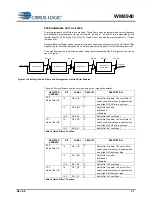
seen in Figure 11.
Notch Filter 0
Notch Filter 1
Notch Filter 2
Notch Filter 3
(or low pass)
NF0_EN
HPF Output
To Audio
Interface
NF1_EN
NF2_EN
NF3_EN
NF3_LP
Figure 11 Labelling of Notch Filters and Arrangement of Notch Filter Enables
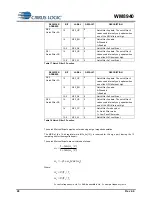
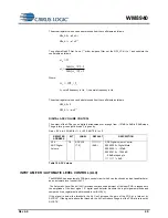
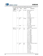
The notch filter coefficients must be entered using a sign / magnitude notation.
REGISTER
ADDRESS
BIT
LABEL
DEFAULT
DESCRIPTION
R16
Notch Filter 0A
15
NF0_UP
0
Notch filter 0 update. The notch filter 0
values used internally only update when
one of the NF0_UP bits is set high.
14
NF0_EN
0
Notch filter 0 enable:
0=Disabled
1=Enabled
13:0
NF0_A0
0
Notch filter 0 a0 coefficient
R17
Notch Filter 0B
15
NF0_UP
0
Notch filter 0 update. The notch filter 0
values used internally only update when
one of the NF0_UP bits is set high.
13:0
NF0_A1
0
Notch filter 0 a1 coefficient
Table 15 Notch Filter 0 Function
REGISTER
ADDRESS
BIT
LABEL
DEFAULT
DESCRIPTION
R18
Notch Filter 1A
15
NF1_UP
0
Notch filter 1 update. The notch filter 1
values used internally only update when
one of the NFU bits is set high.
14
NF1_EN
0
Notch filter 1 enable.
0=Disabled
1=Enabled
13:0
NF1_A0
0
Notch filter 1 a0 coefficient
R19
Notch Filter 1B
15
NF1_UP
0
Notch filter 1 update. The notch filter 1
values used internally only update when
one of the NFU bits is set high.
13:0
NF1_A1
0
Notch filter 1 a1 coefficient
Table 16 Notch Filter 1 Function


