


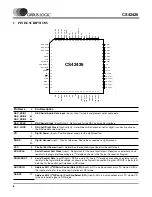


CS42426
16
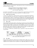
the PLL. In this latter scenario the PLL output becomes the internal master clock. The supported PLL out-
put frequencies are shown in Table 3 below.
The serial bit clock, DAC_SCLK and/or ADC_SCLK, must be synchronous to the corresponding
DAC_LRCK/ADC_LRCK and be equal to 128x, 64x, 48x or 32x Fs depending on the interface format
selected and desired speed mode. One Line Mode #1 is supported in Slave Mode. One Line Mode #2 is
not supported. Refer to Table 4 for required clock ratios.
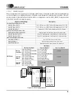
3.5
Digital Interfaces
3.5.1
Serial Audio Interface Signals
The CS42426 interfaces to an external Digital Audio Processor via two independent serial ports, the
DAC serial port, DAC_SP and the ADC serial port, ADC_SP. The digital output of the internal ADCs use
the ADC_SDOUT pin and can be configured to use either the ADC or DAC serial port timings. These con-
figuration bits and the selection of Single, Double or Quad Speed mode for DAC_SP and ADC_SP are
found in register “Functional Mode (address 03h)” on page 33.
The serial interface clocks, ADC_SCLK for ADC_SP and DAC_SCLK for DAC_SP, are used for trans-
mitting and receiving audio data. Either ADC_SCLK or DAC_SCLK can be generated by the CS42426
(master mode) or it can be input from an external source (slave mode). Master or Slave mode selection is
made using bits DAC_SP M/S and ADC_SP M/S in register “Misc Control (address 05h)” on page 36.
The Left/Right clock (ADC_LRCK or DAC_LRCK) is used to indicate left and right data frames and the
start of a new sample period. It may be an output of the CS42426 (master mode), or it may be generated
by an external source (slave mode). As described in later sections, particular modes of operation do allow
the sample rate, Fs, of the ADC_SP and the DAC_SP to be different, but must be multiples of each other.
The serial data interface format selection (left/right justified, I
2
S or one line mode) for the ADC serial port
data out pin, ADC_SDOUT, and the DAC input pins, DAC_SDIN1:3, is configured using the appropriate
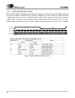
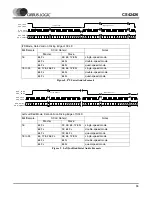
Single Speed
Double Speed
Quad Speed
One Line Mode #1
OMCK/LRCK Ratio
256x, 512x
128x, 256x
128x
256x
SCLK/LRCK Ratio
32x, 48x, 64x, 128x
32x, 64x
32x, 64x
128x
Table 4. Slave Mode Clock Ratios
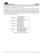
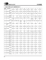
Sample
Rate
(kHz)
PLL Output (MHz)
Single Speed
(4 to 50 kHz)
Double Speed
(50 to 100 kHz)
Quad Speed
(100 to 192 kHz)
256x
256x
256x
32
8.1920
-
-
44.1
11.2896
-
-
48
12.2880
-
-
64
-
16.3840
-
88.2
-
22.5792
-
96
-
24.5760
-
176.4
-
-
45.1584
192
-
-
49.1520
Table 3. Common PLL Output Clock Frequencies


