


6
DS242RD1B1
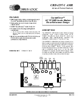
CRD4297-1 AMR
CrystalClear™ AC '97 AMR Audio Modem Riser Reference
CIRRUS LOGIC ADVANCED PRODUCT DATABOOK
capable of driving stereo headphones with imped-
ances greater than 32
Ω
or powered speakers.
R37/38 are added for short-circuit protection. An
optical S/PDIF (IEC 958 consumer) output is also
supported.
Figure
17
: Microphone Pre-amp and Bias
A Motorola MC33078D low noise dual op-amp
provides an +18 dB gain stage for the microphone
and buffers the phantom power supply for the mic.
The phantom power is derived from the +5 V ana-
log supply and buffered by U1A to provide a max-
imum of 4.2 V with no load and a minimum of
2.0 V under a 0.8 mA load on the ring, as required
by the PC 99 System Design Guide, Chapter 17,
Audio Components [5].
Component Selection
Great attention was given to the particular compo-
nents on the CRD4297-1 AMR board with cost,
performance, and package selection as the most im-
portant factors. Listed are some of the guidelines
used in the selection of components:
•
no components smaller than 0805 package
•
use single package components, no resistor
packs
•
right-angled headers for all internal connec-
tions to provide sufficient headroom for the
jacks
•
dual footprint for XTAL. Standard H49U with
GND pad and small circular CA-301 pin-in-
hole package
•
Dual footprint for +5 V and +3.3 V regulators.
Surface mount and pin-in-hole package are
supported.
EMC Components
A number of capacitors and inductors are included
to help the board meet EMC compliance tests, such
as FCC Part 15. Modifying this selection of compo-
nents without EMC testing could cause EMC com-
pliance failure.
GROUNDING AND LAYOUT
Partitioned Voltage and Ground Planes
The pinout of the CS4297 allows the ground split to
completely separate digital signals on one side and
analog signals on the other. This split is located
very close to the CS4297 so analog and digital
ground return currents originating from the
CS4297 may flow through their respective ground
planes. A bridge is made across the split to main-
tain the proper reference potential for each ground
plane.
The area around the crystal oscillator and the two
XTAL signals is filled with copper on the top and
bottom sides and attached to digital ground. This
ground plane serves to keep noise from coupling
onto these pins. All data converters are highly sus-
ceptible to noise on the crystal pins.
A separate chassis ground provides a reference
plane for all of the EMC components. The chassis
ground plane is connected to the analog ground
plane at the external jacks.
CS4297 Layout Notes
Please refer to the CS4297 Data Sheet [3] on how
the area under the chip should be partitioned and
how the bypass capacitors should be placed. Pay
close attention to the suggestions for the bypass ca-
pacitors on REFFLT, AFLT1, AFLT2, and the
power supply capacitors. The pinout of the CS4297
is designed to keep digital and analog signals from
crossing when laying out the board.
Содержание CRD4297-1 AMR
Страница 27: ... Notes ...
Страница 28: ......


