


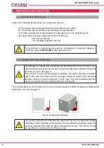


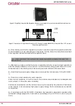


Figure 5:
Cable entry points of the OPTIM FR P&P models.
3.5.-POWER CIRCUIT
Connect input terminals L1, L2 and L3 (power circuit) to the mains using a cable with a suitable
cross-section, in accordance with the LVR, ITC-BT-19.
Generally, the phase cables are according to the following colour code: L1 (black), L2 (brown),
L3 (grey).
In order to determine the size of the phase cables, consider the nominal current I
n
indicated on
the device label, and it should be able to withstand transient overloads of 1.5 times I
n
.
3.6.- EXTERNAL CIRCUIT BREAKER AND PROTECTION ELEMENTS
If the capacitor bank does not have an internal switch or isolation switch, it must be connected
to a line that has an external switch or isolation switch.
The protection elements, isolation switches and/or switches that are added exter-
nally to the capacitor bank must be of a minimum size to withstand a current 1.5
times greater than what is indicated on the label (LVR, ICT-BT-48)
If an earth leakage protection for the capacitor bank is installed, its sensitivity and
trip delay must be adjustable.
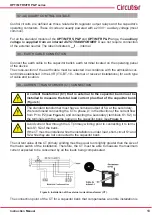
When the capacitor bank is connected to the mains, it is recommended that the current
transformer (CT) is placed on the phase going to L1 (black cable).
Outputs S1 and S2 of the CT must be connected to the terminals with the same name.
12
OPTIM FRS/FR P&P series
Instruction Manual


