background image

05

Before installation

Take into consideration this section before start wiring 

connections of the Charge Point.

1   —   E L E C T R I CA L   P R OT E C T I O N S 

Charge point may not include elements of electrical protection.

If this equipment has internal electrical protections, are installed in each 
socket-outlet for the protection of the user against an electrical failure, 
according to the international standard IEC 61851-1:2017.

In order to guarantee the total protection of the users and the installation 
(power supply line included) in front of any electrical hazard, it is mandatory 
to install a main circuit breaker (MCB) and a residual current device (RCD) 
upstream of the charge point.

These electrical protections and the rest of the installation have to be 
aligned with the local and national rules. The selectivity of the protections 
has to be guaranteed at all times.

2   —   P OW E R   S U P P LY   L I N E   D I M E N S I O N I N G 

The dimensioning of the input power supply line of the charge point must 
be checked by a qualified electrician. Note that various factors such as 
cable length between distribution board and charge point, maximum output 
current of the charge point may have influence of the selected cable.

In such cases, increasing the cable cross-section it is required to adapt the 
temperature resistance of the power supply line.

3   —   M A X I M U M   O U T P U T   C U R R E N T 

Please refer to the TECHNICAL DATA section to consult the default factory 
settings from maximum output current of the charge point.  
Depending on the model this value may vary.

B

Electrical wiring considerations

Содержание Master Series

Страница 1: ...Installation User Manual Post eVolve Rapid Series ...

Страница 2: ...s manual can be reproduced copied translated or transmitted in any form or by any means without the prior written permission of the original manufacturer Information provided in this manual is intended to be accurate and reliable However the original manufacturer assumes no responsibility for its use or for any infringements upon the rights of third parties that may result from its use All other p...

Страница 3: ...iring considerations 05 C Important Electrical Safety Instructions 06 D EVSE Classification 07 3 Overview 08 4 Dimensions 10 5 Installation 12 A Space requirements 13 B Foundation 14 C Opening 15 D Positioning 16 E Unit fixation 17 F Metal plate 17 G Wiring 18 H Verification 19 6 How to use Basic Post 20 7 Technical Data 22 8 Need help 24 ...

Страница 4: ...02 Post eVolve Rapid Manual 1 ...

Страница 5: ...NTION Indicates that the damage to property can occur if appropiate precautions are not taken So hello THE FOLLOWING SYMBOLS ARE USED FOR IMPORTANT SAFETY INFORMATION IN THIS DOCUMENT Compliant with IEC 61851 Electric vehicle conductive charging system IEC 61851 1 and IEC 61851 23 Compliant with IEC 62196 Plugs sockets outlets vehicle connectors and vehicle inlets Conductive charging of electric v...

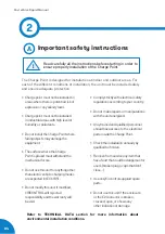
Страница 6: ...es Donotusethisunitforanythingother thanelectricvehiclechargingmodes areexpectedinIEC61851 Donotmodifythisunit Ifmodified CIRCONTROLwillrejectall responsibilityandthewarrantywill bevoid Complystrictlywithelectricalsafety regulationsaccordingtoyourcountry Donotmakerepairsormanipulations withtheunitenergized Onlytrainedandqualifiedpersonnel shouldhaveaccessto theelectrical partsinsidetheChargePoint ...

Страница 7: ...t These electrical protections and the rest of the installation have to be aligned with the local and national rules The selectivity of the protections has to be guaranteed at all times 2 POWER SUPPLY LINE DIMENSIONING The dimensioning of the input power supply line of the charge point must be checked by a qualified electrician Note that various factors such as cable length between distribution bo...

Страница 8: ...necessary to handle equipment that is plugged in be sure hands are dry and when possible wear nonconductive gloves protective clothes and shoes with insulated soles Never handle electrical equipment when hands feet or body are wet or perspiring or when standing on a wet floor Important Electrical Safety Read carefully all the instructions before starting in order to ensure properly handling of ele...

Страница 9: ...Permanently connected 2 Power supply Output DC EV supply equipment 3 Environmental conditions Indoor and outdoor 4 Access Equipment for locations with restricted access and Equipment for locations with non restricted access 5 Mounting method Stationary equipment Ground mounted floor mounted 6 Protection against electric shock Class I 7 Charging modes Mode 4 ...

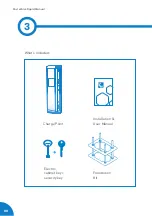
Страница 10: ...08 Post eVolve Rapid Manual 3 What s included Charge Point Installation User Manual Foundation Kit Electric cabinet key security key ...

Страница 11: ...lation 7 Base 8 Start button 9 Stop button 10 Cable roller 11 Cable gland 12 Screen 13 RFID reader 14 Credit card payment 6 7 8 5 5 9 6 10 1 5 3 2 6 7 5 5 6 11 10 1 4 5 3 2 6 7 12 5 5 14 6 11 10 13 Basic Serie Master Serie Satellite Serie Depending on the model the components can vary 11 ...

Страница 12: ...10 Post eVolve Rapid Manual 4 ...

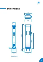
Страница 13: ...11 Dimensions 446 234 1750 80 281 Measures in mm 479 288 438 1064 1198 ...

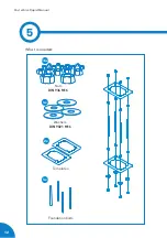
Страница 14: ...12 Post eVolve Rapid Manual 5 What is needed Nuts DIN 934 M16 Washers DIN 9021 M16 Templates Foundation bolts 16x 2x 4x 4x ...

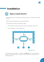
Страница 15: ...ngly to your country specifications The next picture shows how it should be installed Do not install near areas where water or fluids can penetrate into the unit Do not install the unit on unstable terrain x If Bollard Impact Protector is installed keep 500 mm as a minimum distance in order to give enough space to open the frontal door of the Charge Point for maintenance tasks ...

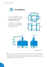
Страница 16: ...must be placed in the ground taking into consideration the following measures Note If there is any further doubt about the terrain regarding the installation of this unit due to the weight and dimensions it will be necessary to define a final solution to install the unit It shall be performed an specific technical project made by an architectural firm prior to its installation 220 130 500 300 Fron...

Страница 17: ... the Tamper switch to operate the Charge Point Tamper Switch The Charge Point has a security switch antitamper protection installed that will avoid any charging session if the doors are opened It has three positions 1 Operative postition The Charge Point is closed 2 Error position The Charge Point is opened without supervision 3 Maintenance position The Charge Point is opened under maintenance Pul...

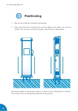
Страница 18: ...Place the Charge Point through the four foundation bolts Make sure that the Charge Point pre holes of the metal plate match with the cable glands Post eVolve Rapid can be placed at outdoor or indoor areas to charge electric vehicles This product series is designed to be placed on the ground ...

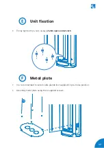
Страница 19: ...ly tighten the 4 nuts using a 24mm open end wrench E Unit fixation It is recommended to install cable glands not supplied in pre holes position Assembly metal plate using the 4 supplied screws F Metal plate 4x ...

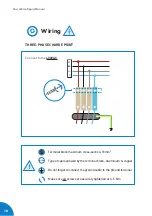
Страница 20: ...ARGE POINT Connect to the 400VAC Do not forget to connect the ground cable to the ground terminal Terminal block maximum cross section 16mm2 Type of cable allowed by the terminal block Aluminium copper Make sure all screws are securely tightened at 4 5 Nm S Al Cu ...

Страница 21: ...bles should remain inside 4 CHECK THE PLUGS Plugs should be in good conditions before starting the unit 5 ELECTRICAL PROTECTIONS If the unit includes electrical protections rearm all of them 6 CHECK THE BEACON INDICATOR The beacon indicator should light properly Here s the reference 7 OPERATION Check no abnormal noise appears while the unit is charging 8 PREVENTIVE MAINTENANCE It is recommended to...

Страница 22: ...51 Now to start a new charge transaction simply plug the cable Once the cable is plugged you are allowed to press start button which is still in green colour At this moment the charge transaction is about to start The LED beacon shows a fix blue B status according to IEC 61851 and the start button blinks in green which means that the car and the charging station have communication between them Go ...

Страница 23: ... LED beacon turns back to green A status according to IEC 61851 Until the status of stop button does not change from red to off the charging station is not available to start a new charging transaction whenever it is required D Charged When the EV is fully charged it turns to Standby step in which both LED beacon and start button are green F Error The Charge Point has an error and it is not availa...

Страница 24: ...ports AC Power Supply 3P N PE AC Input Voltage 400V 10 three phase Power Factor 0 98 Efficiency 94 at nominal output power Frequency 50 60Hz Required power supply capacity 27 kVA Maximum AC input current 39 A Maximum output power 25 kW Maximum output current 70 A Output voltage 150 920 Vdc Compliance CE Combo 2 DIN 70121 ISO15118 IEC61851 1 IEC61851 23 IEC61851 21 2 Enclosure material Aluminium AB...

Страница 25: ...e Post Basic Safety Protections RCD type B 30mA MCB curve C RCD type B 30mA MCB curve C RCD type B 30mA MCB curve C Operating Temperature 25ºC to 45ºC Low Temp Kit 25ºC to 45ºC Low Temp Kit 25ºC to 45ºC Low Temp Kit Environment Outdoor Indoor Outdoor Indoor Outdoor Indoor Dimensions W x H x D 480 x 1750 x 290 mm 480 x 1750 x 290 mm 480 x 1750 x 290 mm Weight 70 kg 70 kg 65 kg Cable support Integra...

Страница 26: ...24 Post eVolve Rapid Manual 8 ...

Страница 27: ...25 Need help In case of any query or further information please contact our Post Sales Department 34 937 362 940 34 937 362 941 support circontrol com circontrol com ...

Страница 28: ...CIRCONTROL Post eVolve Rapid Series Manual A comprehensive guide on how to install and use your eVolve Rapid V2 3 December edition 2021 CIRCONTROL S A ALL RIGHTS RESERVED R474 ...

Отзывы: