


CS
-
100
-
P2100 Series | User Manual
24
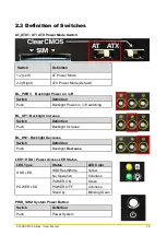
1.5 System I/O
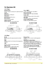
1.5.1 Front
Antenna Hole
Used to connect an antenna for optional wireless
module
SIM Card
Used to insert a SIM card
IGN Switch
Used to set up IGN function
Reset Button
Used to reset the system
AT/ATX Switch
Used to select AT or ATX power mode
Clear CMOS
Used to clear CMOS to reset BIOS
Removable HDD
Used to insert a 2.5” SATA HDD/SSD
Power LED
Indicates the power status of the system
HDD LED
Indicates the status of the hard drive
Power On/Off Switch
Power-on or power-off the system
CS-100/P2102
CS-100/P2102E
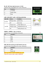
1.5.2 Rear
DC IN
Used to plug a DC power input with terminal
block
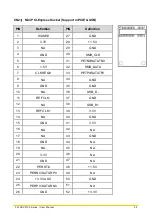
VGA
Used to connect to a monitor with analog signal
interface
LAN
Used to connect to local area network
USB3.2 Gen2
Used to connect to USB 3.2 Gen2/3.2
Gen1/2.0/1.1 compatible devices
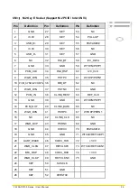
Display Port
Used to connect a monitor with DisplayPort
interface
Digital I/O Terminal Block
The Digital I/O terminal block supports 16
isolated DIO (8 digital input and 8 digital output)
Remote Power On/Off Terminal Block
Used to connect to remote power on/off switch
Universal I/O Bracket (For P2102E)
Used to expand I/O for Mini-PCIe module or
PCI(e) card
CS-100/P2102
CS-100/P2102E
Содержание CS-100/P2100 Series
Страница 14: ...CS 100 P2100 Series User Manual 14 Chapter 1 Product Introductions ...
Страница 26: ...CS 100 P2100 Series User Manual 26 Chapter 2 Switches Connectors ...
Страница 27: ...CS 100 P2100 Series User Manual 27 2 1 Location of Switches and Connectors 2 1 1 Top View 2 1 2 Bottom View ...
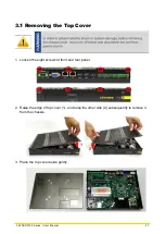
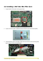
Страница 36: ...CS 100 P2100 Series User Manual 36 Chapter 3 System Setup ...
Страница 60: ...CS 100 P2100 Series User Manual 60 ...
Страница 62: ...CS 100 P2100 Series User Manual 62 Chapter 4 BIOS Setup ...
Страница 81: ...CS 100 P2100 Series User Manual 81 Chapter 5 Product Application ...
Страница 84: ...CS 100 P2100 Series User Manual 84 ...
Страница 91: ...CS 100 P2100 Series User Manual 91 Reference Input Circuit Reference Output Circuit ...
Страница 92: ...CS 100 P2100 Series User Manual 92 Chapter 6 Optional Modules Accessories Pin Definitions and Settings ...


