background image


CO

-

100/P1101 

Series  |  User  Manual 


29


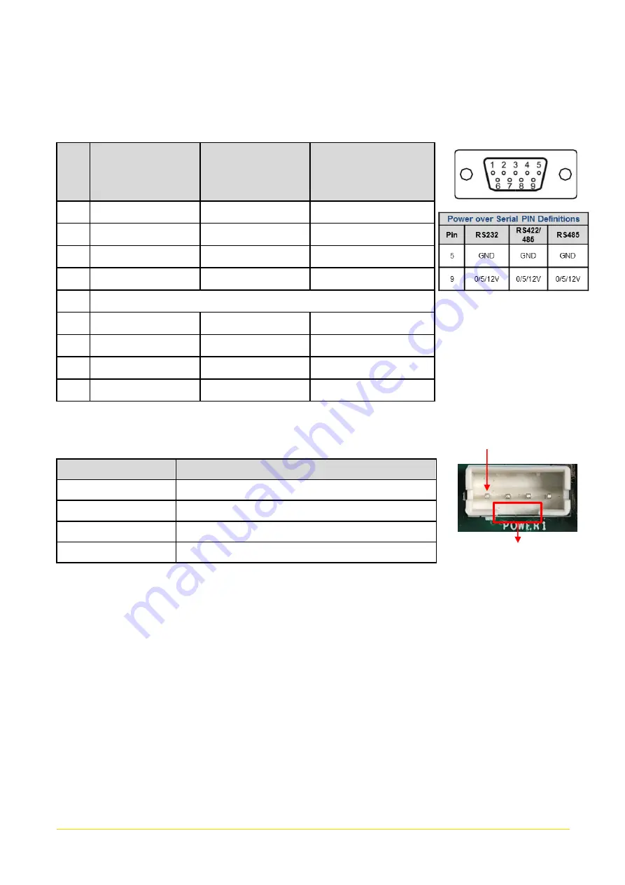
COM1_1 / COM2_1 / COM3_1 / COM4_1: RS232 / RS422 / RS485 Connector 

Connector Type: 9-pin D-Sub 

Pin


RS232 

Definition


RS422 / 485   

Full Duplex 

Definition


RS485   

Half Duplex 

Definition


DCD 

TX- 

DATA - 

RXD 

TX+ 

DATA + 

TXD 

RX+ 


DTR 

RX- 


GND 

DSR 


RTS 


CTS 


RI 


POWER1/ POWER2: Power Connector 

Connector Type: 1x4 4-pin Wafer, 2.0mm pitch 

Pin 

Definition 

+5V 

GND 

GND 

+12V 


Pin 1


Gap


Содержание CO-100/P1101 Series

Страница 1: ...Open Frame Panel PC TFT Full HD 16 9 Panel PC with Intel Atom Pentium Processor Version V1 00 Convertible Display Module CO 100 P1101 Series User Manual ...

Страница 2: ...1C R10 P1101 Series 14 1 4 Hardware Specification 14 1 5 System I O 18 1 5 1 Front 18 1 5 2 Rear 18 1 5 3 Left 19 1 5 4 Right 19 Chapter 2 Switches Connectors 20 2 1 Location of Switches and Connectors 21 2 1 1 Top View 21 2 1 2 Bottom View 22 2 2 Switches and Connectors Definition 23 2 3 Definition of Switches 24 2 4 Definition of Connectors 26 Chapter 3 System Setup 30 3 1 Removing the Top Cover...

Страница 3: ...ole Redirection 59 4 3 7 CPU Configuration 60 4 3 8 Network Stack Configuration 60 4 3 9 CSM Configuration 61 4 3 10 USB Configuration 62 4 4 Chipset Setup 63 4 4 1 North Bridge 63 4 4 2 South Bridge 64 4 4 3 South Cluster Configuration 65 4 5 Security Setup 68 4 5 1 Administrator Password 68 4 5 2 User Password 68 4 6 Boot Setup 69 4 7 Save Exit 70 Chapter 5 Product Application 71 5 1 Digital I O...

Страница 4: ...CO 100 P1101 Series User Manual 4 6 4 Installing VESA Mount 86 6 5 Installing Rack Mount 88 ...

Страница 5: ...ice Acknowledgement Cincoze is a registered trademark of Cincoze Co Ltd All registered trademarks and product names mentioned herein are used for identification purposes only and may be trademarks and or registered trademarks of their respective owners Disclaimer This manual is intended to be used as a practical and informative guide only and is subject to change without notice It does not represe...

Страница 6: ...ance also requires proper cable and cabling techniques Product Warranty Statement Warranty Cincoze products are warranted by Cincoze Co Ltd to be free from defect in materials and workmanship for 2 years 2 Years for PC Module 1 Year for Display Module from the date of purchase by the original purchaser During the warranty period we shall at our option either repair or replace any product that prov...

Страница 7: ...rforming the repair Customers agree to ensure the product or assume the risk of loss or damage during transit to prepay shipping charges and to use the original shipping container or equivalent Customers can be sent back the faulty products with or without accessories manuals cable etc and any components from the system If the components were suspected as part of the problems please note clearly w...

Страница 8: ...cal support team or sales representative for technical support if you need additional assistance Please have following information ready before you call Product name and serial number Description of your peripheral attachments Description of your software operating system version application software etc A complete description of the problem The exact wording of any error messages Conventions Used...

Страница 9: ...nt rating marked on the product 9 Position the power cord so that people cannot step on it Do not place anything over the power cord 10 All cautions and warnings on the equipment should be noted 11 If the equipment is not used for a long time disconnect it from the power source to avoid damage by transient overvoltage 12 Never pour any liquid into an opening This may cause fire or electrical shock...

Страница 10: ...ock Connector Female 1 6 Screw Pack 1 7 Remote Power On Off Terminal Block Connector 1 Note Notify your sales representative if any of the above items are missing or damaged Ordering Information Available Models Model No Product Description CO W121C R10 P1101 E50 R10 21 5 TFT LCD Full HD 16 9 Open Frame Display Modular Panel PC with Intel Atom E3950 Quad Core Processor and P Cap Touch CO W121C R10...

Страница 11: ...CO 100 P1101 Series User Manual 11 Chapter 1 Product Introductions ...

Страница 12: ...M and DIO and the series supports CFM technology offering expansion functions such as Power Ignition Sensing IGN to meet different application needs The integrated structure exclusive adjustable mounting bracket and support for various mounting methods enable a perfect fit in cabinets of different materials and thicknesses The robust design also meets the application needs of harsh industrial envi...

Страница 13: ...th Projected Capacitive Touch Onboard Intel Atom Pentium Processor 1x DDR3L SO DIMM max up to 8GB Designed with Adjustable Mounting Bracket Support Flat Standard VESA Rack Mount Front Panel IP65 Compliant Wide Operating Temperature Cincoze Patent CDS Technology Support ...

Страница 14: ...hscreen Touchscreen Type Projected Capacitive Touch Physical Dimension WxDxH 550 x 343 7 x 63 3 Weight 7 16KG Construction One piece and Slim Bezel Design Mounting Type Flat Standard VESA Rack Mount Mounting Bracket Pre installed Mounting Bracket with Adjustable Design Support 11 different stages of adjustment Protection Ingress Protection Front Panel IP65 Compliant According to IEC60529 Environme...

Страница 15: ...oL Teaming Jumbo Frame PXE RJ45 GbE1 Intel I210 GbE2 Intel I210 USB 4x USB 3 2 Gen1 Type A Serial Port 4x RS 232 422 485 with Auto Flow Control Support 5V 12V DB9 DIO 8x Digital I O 4in 4out 10 Pin Terminal Block Power Mode Switch 1x AT ATX Mode Switch Power Switch 1x Power Switch Reset Button 1x Reset Button Clear CMOS Switch 1x Clear CMOS Switch Remote Power On Off 1x Remote Power On Off Connect...

Страница 16: ... Reverse Power Input Yes Over Voltage Protection Protection Range 51 58V Protection Type shut down operating voltage re power on at the present level to recover Over Current Protection 15A ESD Protection 8kV air 4kV contact Surge Protection 2kV CMOS Battery Backup SuperCap Integrated for CMOS Battery Maintenance free Operation MTBF Time 294 617 hours Operating System Microsoft Windows Windows 10 L...

Страница 17: ...CO 100 P1101 Series User Manual 17 Dimension CO W121C P1101 Unit mm ...

Страница 18: ...ble HDD Used to inserts a 2 5 HDD SSD Power On Off Switch Press to power on or power off the system 1 5 2 Rear DC IN Used to plug a DC power input with terminal block USB 3 0 Used to connect USB 3 0 2 0 device LAN1 LAN2 Used to connect the system to a local area network VGA Used to connect an analog VGA monitor Display Port Used to connect the system with DisplayPort monitor COM1 COM1 supports RS2...

Страница 19: ...rightness of the screen LCD On Off Press to turn on or turn off the display USB 3 0 Used to connect USB 3 0 2 00 device COM3 COM4 COM3 COM4 support RS232 422 485 serial device 1 5 4 Right COM2 COM2 supports RS232 422 485 serial device Digital I O The Digital I O terminal block supports 4 digital input and 4 digital output USB 3 0 Used to connect USB 3 0 2 0 device Mic In Used to connect a micropho...

Страница 20: ...CO 100 P1101 Series User Manual 20 Chapter 2 Switches Connectors ...

Страница 21: ...CO 100 P1101 Series User Manual 21 2 1 Location of Switches and Connectors 2 1 1 Top View ...

Страница 22: ...CO 100 P1101 Series User Manual 22 2 1 2 Bottom View ...

Страница 23: ...nector DC_IN1 3 pin DC 9 48V Power Input with Power Ignition Connector LAN1 LAN Connector LAN2 LAN Connector VGA1 VGA Connector DP1 DisplayPort Connector PWR_SW2 Power Switch Connector DIO1 4DI 4DO Connector MIC_IN1 Mic in Jack LINE_OUT1 Line Out Jack SW1 Super CAP SW COM3 4 with Power Select SW2 COM1 2 with Power Select MINIPCIE1 Mini PCI Express SIM USB3 Socket MINIPCIE2 Mini PCI Express mSATA S...

Страница 24: ..._CMOS Clear CMOS Switch Switch Definition 1 2 Left Normal Status Default 2 3 Right Clear CMOS BL_PWR1 Backlight Power on off Switch Definition Push Backlight Power on off switching BL_UP1 Backlight Increase Switch Definition Push Backlight Increase BL_UP2 Backlight Decrease Switch Definition Push Backlight Decrease RESET1 Reset Button Switch Definition Push Reset System ...

Страница 25: ...FF OFF Location Function DIP5 DIP6 SW1 COM4 0V RI ON Default ON Default 5V ON OFF 12V OFF OFF SW2 COM1 2 with Power Select Location Function DIP1 DIP2 SW2 COM1 0V RI ON Default ON Default 5V ON OFF 12V OFF OFF Location Function DIP3 DIP4 SW2 COM2 0V RI ON Default ON Default 5V ON OFF 12V OFF OFF LED1 Power HDD Access LED Status LED LED Color Status POWER Green POWER ON HDD Blinking Yellow HDD Read...

Страница 26: ...A 21 GND 39 RESERVED 4 GND 22 PERST 40 GND 5 NA 23 PERN0 USB3RN0 SATARP0 41 3 3V 6 1 5V 24 3 3V 42 NA 7 CLKREQ 25 PERP0 USB3RP0 SATARN0 43 GND 8 SIM_VCC 26 GND 44 NA 9 GND 27 GND 45 NA 10 SIM_DATA 28 1 5V 46 NA 11 REFCLK 29 GND 47 NA 12 SIM_CLK 30 SMB_CLK 48 1 5V 13 REFCLK 31 PETN0 USB3TN0 SATATN0 49 NA 14 SIM_Reset 32 SMB_DATA 50 GND 15 GND 33 PETP0 USB3TP0 SATATP0 51 NA 16 SIM_VPP 34 GND 52 3 3V...

Страница 27: ...USB_D 3 NA 21 GND 39 3 3V 4 GND 22 PERST 40 GND 5 NA 23 PERN0 SATARP0 41 3 3V 6 1 5V 24 3 3VAUX 42 NA 7 CLKREQ 25 PERP0 SATARN0 43 GND 8 NA 26 GND 44 NA 9 GND 27 GND 45 NA 10 NA 28 1 5V 46 NA 11 REFCLK 29 GND 47 NA 12 NA 30 SMB_CLK 48 1 5V 13 REFCLK 31 PETN0 ATATN0 49 NA 14 NA 32 SMB_DATA 50 GND 15 GND 33 PETP0 SATATP0 51 NA 16 NA 34 GND 52 3 3V 17 NA 35 GND 18 GND 36 USB_D ...

Страница 28: ...D LAN1 LAN2 LAN LED Status Definition Act LED Status Definition Blinking Yellow Data Activity Off No Activity Link LED Status Definition Steady Green 1Gbps Network Link Steady Orange 100Mbps Network Link Off 10Mbps Network Link Do not apply power to this connector This port is used to connect a SWITCH WARNING Please disconnect the power source before mounting the DC power cables or connecting the ...

Страница 29: ...tor Type 9 pin D Sub Pin RS232 Definition RS422 485 Full Duplex Definition RS485 Half Duplex Definition 1 DCD TX DATA 2 RXD TX DATA 3 TXD RX 4 DTR RX 5 GND 6 DSR 7 RTS 8 CTS 9 RI POWER1 POWER2 Power Connector Connector Type 1x4 4 pin Wafer 2 0mm pitch Pin Definition 1 5V 2 GND 3 GND 4 12V Pin 1 Gap ...

Страница 30: ...CO 100 P1101 Series User Manual 30 Chapter 3 System Setup ...

Страница 31: ...CO 100 P1101 Series User Manual 31 3 1 Removing the Top Cover 1 Loosen the 8 screws of front and rear panel then place them aside 2 Remove the cover from the chassis 3 Place the top cover gently ...

Страница 32: ...ocate the SO DIMM sockets 2 Tilt the SO DIMM module at a 45 degree angle and insert it to SO DIMM socket until the gold pated connector of module contacted firmly with the socket 3 Press the modules down until it s fixed firmly by the two locking latches on each side 45 ...

Страница 33: ...ble for full or half size card 1 Locate the Mini PCIe slot 2 Insert the Mini PCIe card at a 45 degree angle and insert it to the slot until the gold pated connector of module contacted firmly with the slot 3 Press down the module and fasten two screws to secure the module 45 ...

Страница 34: ...anual 34 4 If you have a Half size Mini PCIe card make sure use extender to make it Full size as shown below 3 4 Installing Antennas 1 Remove the antenna hole covers at front panel 2 Have antenna jack penetrate through the hole ...

Страница 35: ...CO 100 P1101 Series User Manual 35 3 Put on washer and fasten the nut with antenna jack 4 Assemble the antenna and antenna jack together 5 Attach the RF connector at another end of cable onto the module ...

Страница 36: ...r Manual 36 3 5 Installing CPU Thermal Pad 1 Place the thermal pad on the CPU heatsink Before assembling the system s chassis cover please make sure the protective film on the Thermal Pad has been removed CAUTION thermal pad ...

Страница 37: ...CO 100 P1101 Series User Manual 37 3 6 Assembling the System 1 Put on the cover 2 Fasten the 8 screws to fix the cover ...

Страница 38: ...01 Series User Manual 38 3 7 Installing a SATA Hard Drive 1 Loosen 2 screws on front panel to remove cover plate 2 Turn over the unit to have the bottom side face up and loosen 1 screw 3 Pull out the HDD bracket ...

Страница 39: ...place the HDD bracket on it Ensure the direction of bracket is correct and use 4 provided screws to assemble HDD and HDD bracket together 5 Align the HDD bracket with the entrance of HDD bay And insert the HDD bracket until the connector of HDD contact the SATA connector firmly ...

Страница 40: ...CO 100 P1101 Series User Manual 40 3 8 Installing a SIM Card 1 Loosen 2 screws on front panel to remove cover plate 2 SIM card slot is at the front panel of the system 3 Insert the SIM card ...

Страница 41: ...e the CO Display Module The complete shipping product is the CO display module already installed on the P1100 This chapter will introduce how to dissemble CO display module and P1100 1 Remove the 6 screws on the display module 2 Disconnect the modules ...

Страница 42: ...re the screw positions are fastened at the default positions as indicated in the following picture The default positions are the correct positions for Standard Mount so it does not need to change the screw positions additionally for Standard Mount 1 Put the CO 100 P1100 module onto the rack s back side ...

Страница 43: ...ixing the module through the screw holes as shown below User can also prepare 16 x M4 screws for fixing the module through the oblong holes as shown below The round screw holes have threads while the oblong holes do not have threads Please select the screw fixing hole position according to the on site environment NOTE ...

Страница 44: ...User Manual 44 3 11 Flat Mount 1 Locate the left and right side mounting brackets 2 Remove the two screws on the left and right side mounting brackets 3 Loosen the three screws on the left and right side mounting brackets ...

Страница 45: ...ickness The thickness is measured 3mm in this example 5 According to the thickness 3mm for the example push down the left and right side mounting brackets to the place at screw hole 3mm 6 Fasten the two screws on the left and right side mounting brackets 3mm ...

Страница 46: ... Series User Manual 46 7 Fasten the three screws on the left and right side mounting brackets 8 Locate the top and bottom side mounting brackets 9 Remove the two screws on the top and bottom side mounting brackets ...

Страница 47: ...ounting brackets 11 According to the thickness 3mm for the example push down the top and bottom side mounting brackets to the place at screw hole 3mm 12 Fasten the two screws on the top and bottom side mounting brackets 13 Fasten the three screws on the top and bottom side mounting brackets ...

Страница 48: ...01 Series User Manual 48 14 Put the CO 100 module onto the rack back side 15 Fasten the screws from the rack s front side Please prepare 12 x M4 screws for fixing the module through the screw holes as shown below ...

Страница 49: ...CO 100 P1101 Series User Manual 49 User can also prepare 16 x M4 screws for fixing the module through the oblong holes as shown below ...

Страница 50: ...mble the mounting brackets Before the installation of VESA mount and rack mount user need to disassemble the mounting brackets on the CO display module first 1 Remove the 8 screws 2 Remove the 3 screws on the left and right side of mounting brackets ...

Страница 51: ...CO 100 P1101 Series User Manual 51 3 Remove the 3 screws on the top and bottom side of mounting brackets 4 Remove the four mounting brackets ...

Страница 52: ...CO 100 P1101 Series User Manual 52 Chapter 4 BIOS Setup ...

Страница 53: ...elect item Esc Quit the BIOS Setup Enter Select item Page Up Increases the numeric value or makes changes Page Down Decreases the numeric value or makes changes Tab Select setup fields F1 General help F2 Previous value F3 Load Optimized defaults F10 Save configuration and Exit Main Menu The main menu lists the setup functions you can make changes to You can use the arrow keys to select the item Th...

Страница 54: ...he Main Menu as shown below will appears on the screen Use arrow keys to move among the items and press Enter to accept or enter a sub menu 4 2 1 System Date Set the date Please use Tab to switch between date elements 4 2 2 System Time Set the time Please use Tab to switch between time elements ...

Страница 55: ...gure and improve your system and allows you to set up some system features according to your preference 4 3 1 Trusted Computing Settings Security Device Support Enabled Enables or disables Security Device Support function SHA 1 PCR Bank Enabled Enables or disables SHA 1 PCR Bank function ...

Страница 56: ...erarchy function Endorsement Hierarchy Enabled Enables or disables Endorsement Hierarchy function Physical Presence Spec Version 1 3 Allows you to select which mode Physical Presence Spec Version will operate Configuration options 1 2 1 3 4 3 2 ACPI Settings Enable ACPI Auto Configuration Disabled Enables or disables BIOS Advanced Configuration Power Interface ACPI auto configuration Enable Hibern...

Страница 57: ... is pressed Suspend Disabled Disables entering suspend state S3 suspend to RAM Enables suspend to RAM state Lock Legacy Resources Enabled Enables or disables Lock Legacy Resources 4 3 3 F81866 Super IO Configuration Set Parameters of Serial Ports User can Enable Disable the serial port and Select an optimal setting for the Super IO Device Serial Port 1 4 Configuration ...

Страница 58: ...select Serial Port Mode Configuration options RS232 RS422 RS485 Full Duplex RS485 Half Duplex Watch Dog Disabled Enables or disables watch dog function Watch Dog Mode Sec Allows to set watchdog timer unit Sec or Min Watch Dog Timer 0 Allows you to set watchdog timer s value in the range of 0 to 255 4 3 4 Hardware Monitor This screen displays the current status of all monitored hardware devices com...

Страница 59: ...off state Disabled Disables wake system from S5 Fixed Time Sets a fixed time HH MM SS to wake system from S5 Dynamic Time Sets an increase minute s from current time to wake system from S5 4 3 6 Serial Port Console Redirection Console Redirection Disabled Allow users to enable or disable COM1 COM2 COM3 COM4 console redirection function ...

Страница 60: ...es to enable in each processor package Intel Virtualization Technology Enabled Enables or disables Intel Virtualization Technology Virtualization enhanced by Intel Virtualization Technology will allow a platform to run multiple operating systems and applications in independent partitions With virtualization one computer system can function as multiple virtual systems 4 3 8 Network Stack Configurat...

Страница 61: ... UEFI option ROM Legacy only Allows booting from operating systems that only support legacy option ROM UEFI only Allows booting from operating systems that only support UEFI option ROM Network PXE Do not launch Controls the execution of UEFI and Legacy PXE Network Preboot eXecution Environment option ROM Do not launch Disables option ROM execution UEFI Enables UEFI option ROM only Legacy Enables l...

Страница 62: ...evise other than network storage or video 4 3 10 USB Configuration Legacy USB Support Enabled This item allows you to enable or disable legacy USB support When set to Auto legacy USB support will be disabled automatically if no USB devices are connected XHCI Hand off Enabled Enables or disables XHCI USB3 0 hand off function Use this feature as a workaround for operating systems without XHCI hand o...

Страница 63: ...pset Setup This section allows you to configure chipset related settings according to user s preference 4 4 1 North Bridge This section provides information on the installed memory size and memory onboard graphics related configuration options ...

Страница 64: ...itch Mini PCIE Allows you to change Mini PCIE1 as Mini PCIE or USB3 Mini PCIE2 mSATA Switch Mini PCIE Allows you to change Mini PCIE2 as Mini PCIE or mSATA Amplifier Function Enabled Enables or disables Amplifier Function PSE Enable Selection Enabled Enables or disables PSE Power Sourcing Equipment LAN1 Enabled Enables or disables LAN1 Controller LAN2 Enabled Enables or disables LAN2 Controller ...

Страница 65: ... Configuration PCI Express Configuration PCI Express Root Port 5 MiniPcie2 PCI Express Root Port 5 MiniPcie2 Enabled Enables or disables PCI Express Root Port PCIe Speed Auto Allows you to select PCI Express port speed Configuration options Auto Gen1 Gen2 ...

Страница 66: ...Pcie Enabled Enables or disables PCI Express Root Port PCIe Speed Auto Allows you to select PCI Express port speed Configuration options Auto Gen1 Gen2 SATA Devices SATA Port 0 Port 0 Enabled Enables or disables SATA Port 0 SATA1 SATA Port 1 Port 1 Enabled Enables or disables SATA Port 1 MINIPCIE2 ...

Страница 67: ...after a power failure G3 state Always on Enters to power on state Always off Enters to power off state Last state Enters to the last power state before a power failure sables Wake On Lan Enabled Enables or disables Wake On LAN WOL function BIOS Lock Disabled Enables or disables BIOS the SC BIOS Lock enable feature It is required to be enabled to ensure SMM protection of flash ...

Страница 68: ...his section allows users to configure BIOS security settings 4 5 1 Administrator Password Administrator Password controls access to the BIOS Setup utility 4 5 2 User Password User Password controls access to the system at boot and to the BIOS Setup utility ...

Страница 69: ...n or Off state when system boots up Quiet Boot Allows you to enable or disable Quiet Boot function Fast Boot Allows you to enable or disable Fast Boot function If enabled system boots with initialization of a minimal set of devices required to launch active boot option Hard Drive BBS Priority Allows you to set the order of the legacy devices in this group ...

Страница 70: ...set This item allows you to reset system setup without saving any changes Restore Defaults This item allows you to restore load default values for all the setup options Save as User Defaults This item allows you to save the changes done so far as user defaults Restore User Defaults This item allows you to restore the user defaults to all the setup options ...

Страница 71: ...CO 100 P1101 Series User Manual 71 Chapter 5 Product Application ...

Страница 72: ...I O chip F81866A configuration registers the following configuration procedures must be followed in sequence 1 Enter the Extended Function Mode 2 Configure the configuration registers 3 Exit the Extended Function Mode The configuration register is used to control the behavior of the corresponding devices To configure the register use the index port to select the index and then write data port to a...

Страница 73: ...1101 Series User Manual 73 o 4e 87 o 4e 87 enable configuration o 4e aa disable configuration 5 1 1 3 Relative Registers To program the F81866A configuration registers see the following configuration procedures ...

Страница 74: ...ust write twice to enter Extended mode Select Logic Device WriteByte AddrPort 0x07 WriteByte dataPort 0x06 Select logic device 06h Input Mode Selection Set GP74 to GP77 input Mode WriteByte AddrPort 0x80 Select configuration register 80h WriteByte DataPort 0x0X Set bit 4 7 0 to select GP 74 77 as Input mode Input Value WriteByte AddrPort 0x82 Select configuration register 82h ReadByte DataPort Val...

Страница 75: ...tended mode Select Logic Device WriteByte AddrPort 0x07 WriteByte DataPort 0x06 Select logic device 06h Output Mode Selection Set GP80 to GP83 output Mode WriteByte AddrPort 0x88 Select configuration register 88h WriteByte DataPort 0xXF Set bit 0 3 1 to select GP 80 83 as Output mode Output Value WriteByte AddrPort 0x89 Select configuration register 89h WriteByte DataPort Value Set bit 0 3 0 1 to ...

Страница 76: ...r Extended mode Select Logic Device WriteByte AddrPort 0x07 WriteByte dataPort 0x06 Select logic device 06h WriteByte AddrPort 0x60 Select configuration register 60h High Byte address WriteByte DataPort 0x0A WriteByte AddrPort 0x61 Select configuration register 61h Low Byte address WriteByte DataPort 0x00 Leave the Extended Function Mode WriteByte AddrPort 0xAA Note Cincoze DIO Port base address i...

Страница 77: ...0 bit 0 0 0 1 value h X 1 DO1 7 6 5 4 3 2 1 0 bit 0 0 1 0 value h 2 X DI2 7 6 5 4 3 2 1 0 bit 0 0 1 0 value h X 2 DO2 7 6 5 4 3 2 1 0 bit 0 1 0 0 value h 4 X DI3 7 6 5 4 3 2 1 0 bit 0 1 0 0 value h X 4 DO3 7 6 5 4 3 2 1 0 bit 1 0 0 0 value h 8 X DI4 7 6 5 4 3 2 1 0 bit 1 0 0 0 value h X 8 DO4 5 1 1 7 DIO I O Port Address ...

Страница 78: ...pe Input Signal Voltage Level Signal Logic 0 XCOM 9V Signal Low V 1V XCOM 9V V Signal Low 8V Signal Logic 1 XCOM 3V Input Driving Sink Current Minimal 1 mA Normal 5 mA 4x Digital Output Open Drain DO Signal have to pull up resistor to XCOM for external device the resistance will affect the pull up current Signal High Level Pull up resistor to XCOM Signal Low Level XCOM Sink Current 1A Max ...

Страница 79: ...l 79 5 2 1 DIO Connector Definition DIO1 Digital Input Output Connector Connector Type Terminal Block 1X10 10 pin 3 5mm pitch Pin Definition Pin Definition 1 XCOM DC INPUT 6 DO1 2 DI1 7 DO2 3 DI2 8 DO3 4 DI3 9 DO4 5 DI4 10 XCOM GND ...

Страница 80: ...CO 100 P1101 Series User Manual 80 Chapter 6 Optional Modules and Accessories Pin Definitions and Settings ...

Страница 81: ...trol Function Individual Port 25 5W SW2 IGN Function Switch Set shutdown delay timer when ACC is turned off Pin 1 Pin 2 Pin 3 Pin 4 Definition OFF ON ON ON ON 0 second ON ON OFF 1 minute ON OFF ON 5 minutes ON OFF OFF 10 minutes OFF ON ON 30 minutes OFF ON OFF 1 hour OFF OFF ON 2 hours OFF OFF OFF Reserved 0 second 24V_12V_1 12V 24V Car Battery Switch Pin Definition 1 2 24V Car Battery Input 2 3 1...

Страница 82: ...ng CFM IGN Module 1 Locate the IGN connector on system motherboard as indicated 2 Insert CFM IGN module vertically to the female connector on the system s mainboard and fasten 2 screws to fix it 3 Loosen 2 screws on front panel to remove cover plate ...

Страница 83: ...CO 100 P1101 Series User Manual 83 4 IGN function switch is at the front panel of the system ...

Страница 84: ... indicated 2 Insert the female connector of CFM PoE module to the male connector on system motherboard 3 Turn over the heatsink and paste the thermal pad onto the marked by red squares Before putting on the thermal block in the next step please make sure the protective film on the Thermal Pad has been removed CAUTION ...

Страница 85: ...o fix it 5 Paste the thermal pads onto the heatsink and coil carefully 6 When the system is power on please note that the POE LED will light on if the POE module is properly installed Before assembling the system s chassis cover please make sure the protective films on the Thermal Pads have been removed CAUTION ...

Страница 86: ... the mounting brackets on the CO display module first This series supports VESA mounting that customer can mount system with panel complying with VESA 75mm and 100 mm standard for various usage The 75mm VESA uses blue circle marked screw holes The 100mm VESA uses red circle marked screw holes 1 Put the VESA stand on and align with the mounting holes ...

Страница 87: ...CO 100 P1101 Series User Manual 87 2 Fasten the VESA mount screws to complete the VESA mounting ...

Страница 88: ...k Mount Before the installation of rack mount user need to follow the chapter 3 12 to disassemble the mounting brackets on the CO display module first 1 Locate the screw holes on the PC or monitor module 2 Put on the rack mount base and fasten the screws ...

Страница 89: ...ning 4 screws M5x6 at each side Left Right Bottom 4 Assemble two rack mount brackets by fastening 4 screws M5x12 flat washers and hex nuts at each side For P2002E For P2002 P1001E For P1001 P1101 P2102 P2102E Rack mount bracket holes for 21 Panel PC series For 21 Panel PC series ...

Страница 90: ...registered trademark of Cincoze Co Ltd All other logos appearing in this catalog are the intellectual property of the respective company product or organization associated with the logo All product specifications and information are subject to change without notice ...

Отзывы: