C.I.B. UNIGAS - M039132CD
27
.
ELECTRICAL CONNECTIONS
To execute the electrical connections, proceed as follows:
1
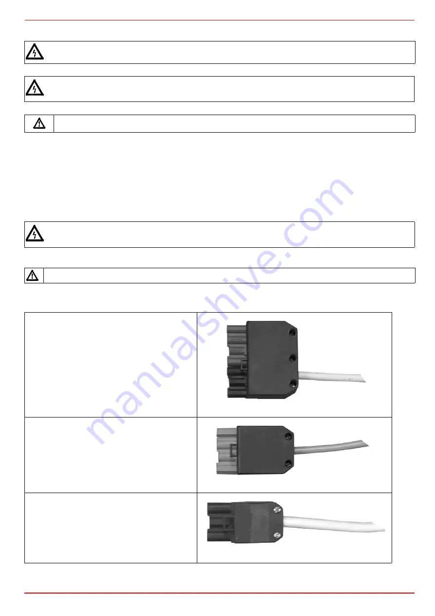
find the pulg or the plugs, according to the model, that comes out from the burnrer:
z
7 pins plug for the power supply (for all models);
z
4 pins plug (for AB - double stage, PR-progressive, MD - fully-modulating);
z
3-pins plug (only for NG/NGX400);
2
execute the electrical connections to the plugs, according to hte burner model (see next paragraph);
3
once all the connections are accomplished, check the fan motor direction (sse next paragraphs)
;
4
now the burner is ready to start up.
Connectors identification
RESPECT THE BASIC SAFETY RULES. MAKE SURE OF THE CONNECTION TO THE EARTHING SYSTEM. DO NOT
REVERSE THE PHASE AND NEUTRAL CONNECTIONS. FIT A DIFFERENTIAL THERMAL MAGNET SWITCH ADE-
QUATE FOR CONNECTION TO THE MAINS.
ATTENTION: before executing the electrical connections, pay attention to turn the plant’s switch to OFF and be sure
that the burner’s main switch is in 0 position (OFF) too. Read carefully the chapter “WARNINGS”, and the “Electrical
connections” section.
WARNING: if the cable that connects the thermostats and the control box should be longer than 3 meters, insert a
sectioning relay following the attached electrical wiring diagram.
The burner is fitted with a bridge between terminals T6 and T8 on the 4-poles plug-TAB (external side link, male con-
nector); if the TAB high/low flame thermostat must be connected, remove the bridge between terminals, before con-
necting the thermostat.
IMPORTANT: before operating the burner, be sure all connectors are linked as shown in the diagrams.
Burner power supply connector
(Fig. 34 - Fig. 36 - Fig. 38)
Probe connection connector
(
fully modulating bur-
ners
, Fig. 40)
Fig. 31
HIGH/LOW flame connector
(
progressive burners
, Fig.
36)
Fig. 32
Fan motor connector
(NG/NGX400
only
)
(Fig. 35 - Fig. 39)
Fig. 33
Содержание IDEA NG280
Страница 45: ...C I B UNIGAS M039132CD 45...


