background image

KR series

6

-

10kVA

user

’s manual 

- 17 - 


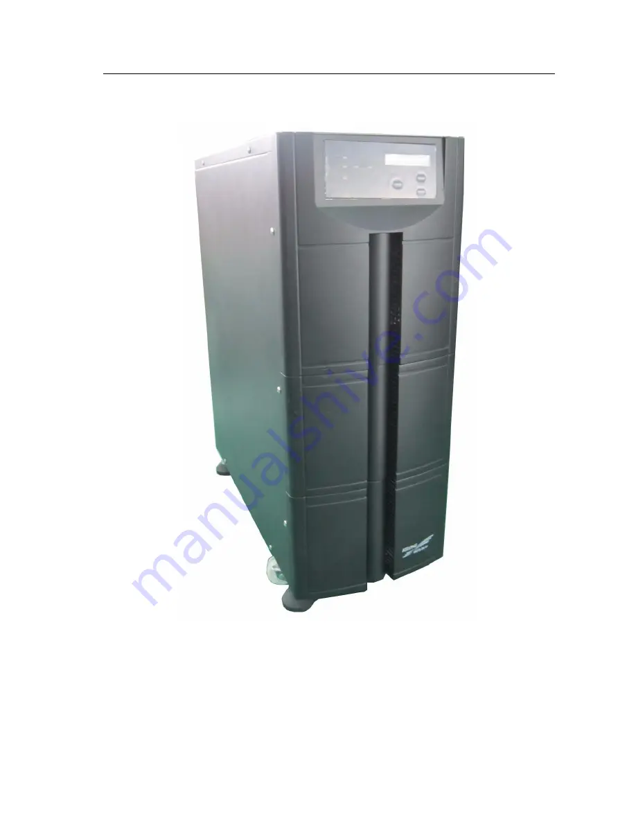
3.3.4 KR6000, KR(/B)1110S, KR(/B)3110S appearance 


3.3-5      KR6000, KR(/B)1110S, KR(/B)3110S appearance 

Содержание KR1110

Страница 1: ...KR Series UPS 6 10 KVA User s Manual...

Страница 2: ...nterface 14 3 3 3 KR6000L KR B 1110 KR B 3110 appearance 15 3 3 4 KR6000 KR B 1110S KR B 3110S appearance 17 4 Installation 19 4 1 Installation Notice 19 4 2 Installation process 20 4 3 Installation p...

Страница 3: ...l system 34 5 4 4 Online start up Parallel System 35 5 4 5 Redundancy and Expansion of Parallel System 35 6 Maintenance and Fault Diagnosis 37 6 1 Maintenance Guide 37 6 1 1 Safety Precaution 37 6 1 2...

Страница 4: ...internal exists high temperature and voltage the equipment installation the operator must comply with relevant safety standards and operational procedures during UPS installation operation and mainten...

Страница 5: ...0 min the UPS chassis could be opened after charge released 4 Battery cable has not separated with AC input Dangerous voltage may exist between battery terminal and ground terminal Battery pack exists...

Страница 6: ...flapper circuit boards IC chips etc also the other end of wrist strap is well grounded Installation with AC input and remove power cable are dangerous Installation with AC input and remove power cabl...

Страница 7: ...uld be stayed away from fire and all the electrical equipment which could cause sparks easily to avoid danger or unnecessary losses Be careful for the rotating fan When remove the fan do not put finge...

Страница 8: ...Fig 2 1 1 The meaning of KR 6kVA series model name Shown as Fig 2 1 1 KR indicates that this product is Kehua KR Series high frequency UPS 6000 indicates that output power of this product is 6kVA L in...

Страница 9: ...ies 6 10KVA UPS the online UPS of sine wave charactering high performance has mainly the following features Great adaptability for AC input Within wide input voltage range there is no need for battery...

Страница 10: ...age protection low battery protection over load protection fast current limit short circuit protection over temperature etc are able to avoid faults caused by manual operation mistake to guarantee rel...

Страница 11: ...Mode Terminal Other Characteristic Back up Time Configure optionally Charge recovery time 20 H 100AH a group 20 H 100AH a group Communication interface RS232 USB interface supports Upslion 2000 softw...

Страница 12: ...mmercial power is normal through PFC it can be boosted to stabilized DC supplied for DC AC inverter to output steady 220VAC and finish battery charge at the same time When commercial power is abnormal...

Страница 13: ...gs or protections are shown in detail in Table 3 1 1 Table 3 1 1 The Functions of Abnormal Status and Warning Protections UPS Status Beep Indicators On Panel LCD Display Protection Warning Normal No b...

Страница 14: ...form amplitude and phase then make them strictly the same to achieve current sharing purposes Any difference of the voltage amplitude or phase may have a great circulation seriously it may cause overl...

Страница 15: ...mode of utility normal solid line is Energy flow of UPS as shown in Fig 3 2 2 DC DC PFC PFC DC DC Bypass Switch Inverter Load Battery Main UPS2 AC Input Bypass Switch Inverter Battery Main UPS1 Fig 3...

Страница 16: ...Inverter Battery Main UPS1 Fig 3 2 4 Working mode of overload 4 Working mode of one machine abnormal solid line is Energy flow of UPS as shown in Fig 3 2 5 Abnormal machine doesn t have output so supp...

Страница 17: ...LCD display illustration LINE When commercial power is normal light on abnormal light off when live wire and neutral wire reverse light fliter three phase in single phase out type is without this func...

Страница 18: ...PS is running press the button for 1 sec UPS will enter battery test model When battery voltage reaches the low voltage point or test time last 10 sec UPS will stop the function When battery is workin...

Страница 19: ...ATTERY Breaker BYPASS Breaker FANS LINE BAR COVER MANUAL MAINTENANCE BYPASS optional OFF BATTERY ON POWER BYPASS EPO USB RS232 RS232 USB EPO FANS LINE BAR COVER MANUAL MAINTENANCE BYPASS optional SNMP...

Страница 20: ...KR series 6 10kVA user s manual 17 3 3 4 KR6000 KR B 1110S KR B 3110S appearance 3 3 5 KR6000 KR B 1110S KR B 3110S appearance...

Страница 21: ...NCE BYPASS optional FANS LINE BAR COVER OFF BATTERY ON POWER BYPASS EPO USB RS232 RS232 USB EPO SNMP optional FANS MANUAL MAINTENANCE BYPASS optional SNMP optional POWER Breaker BATTERY Breaker BYPASS...

Страница 22: ...e installing UPS do not connect the zero line live line and grounding line of Input and output of the UPS reversely or wrongly so as to avoid short circuit Meanwhile Please check whether the voltage o...

Страница 23: ...y manufacturers or authorized engineers 4 3 Installation preparation 4 3 1 Checking the installation site Attention Before installing UPS please ensure sites and environment meet basic conditions pres...

Страница 24: ...pply meet the requirements of devices to take the decreased in current carrying capacity by aging of wire into account 3 Equip Breaker protection for AC input Install breaker or power distribution box...

Страница 25: ...d 4 3 2 Unpacking and inspect the machine 4 3 2 2 Transportation 1 Arrange appropriate transportation and lifting according to the size of packages such as forklift 2 If the volume of packages are too...

Страница 26: ...the breaker of mainframe on the OFF status Be sure not to connect Ground line and Zero line Live line and Zero reversely mutually result in short circuit Ensure good grounding and the voltage between...

Страница 27: ...00 the external structure as below Fig 4 6 1 Installation steps 1 2 Loosen and take down 6 pieces of Hexagon bolt M8 20 Two on both left and right side between Anchor frame and tail margin supporting...

Страница 28: ...ied with when replace batteries Do not wear watch ring or other metal accouterment Use tools with insulation handle No placement of tools or metal on the battery No fire is close to batteries and no s...

Страница 29: ...ct AC output of each parallel system to output power distribution box of parallel system Attention Connection and phase sequence of AC input of each unit of parallel system must be the same ensure byp...

Страница 30: ...AC Output N Fig 4 9 1 KR B 3110 S Connection methods of line Bar 4 9 2 Wire Connection of Parallel system 1 As per the installation process described above install each battery and host UPS separately...

Страница 31: ...is demonstrated as in below figure 4 9 3 4 Parallel Connection for KR B 3110 S is demonstrated as in below figure 4 9 4 BATTERY PE L N N L OUTPUT INPUT INPUT OUTPUT L N N L PE BATTERY N L GND UPS1 L U...

Страница 32: ...UT BATTERY V W W V BATTERY INPUT OUTPUT L N N U PE Power Distribution Box AC OUTPUT N AC OUTPUT L BATTERY BATTERY AC Input W AC Input V AC Input U AC Input N AC Input N AC Input U AC Input V AC Input...

Страница 33: ...rect yes No 6 Check if the cable marks are correct yes No 7 Check if the wiring is trim and the cable colligation comply with technics criterion yes No 8 Check the device installation and wiring is pr...

Страница 34: ...t startup can be avoided 3 Till the UPS startup into steady work status turn on the load equipments with sequence of high power ones first and low power ones later because the startup current of some...

Страница 35: ...y use the grid power directly 2 Make sure that the load is turned off Meanwhile the load capacity shall not exceed the UPS rated output capacity otherwise it will cause the system overload protection...

Страница 36: ...us of UPS When it indicates the UPS is in inverter working mode or battery working mode it can supply power to the load After the UPS has running about 10 minutes without load start the load according...

Страница 37: ...intenance In addition too big circumfluence current will lead to inverter damage If the circumfluence current is bigger than 3A report for maintenance 3 Then close the output switching box s main air...

Страница 38: ...hieve current sharing operation Fig 5 4 2 online Launch Parallel System 5 4 5 Redundancy and Expansion of Parallel System 1 Redundant Function When using N 1 parallel redundant backup design total out...

Страница 39: ...if the quantity is over many the reliability of the whole parallel system will decrease on the contrary and can not reach the aim of improving reliability Therefore we don t suggest using parallel mo...

Страница 40: ...outerments like ring watch wore 3 Don t assume the safe operation procedure as a matter of course If any doubt consult with persons being familiar with the instrument 6 1 2 Periodic Preventative Maint...

Страница 41: ...as gasoline and thinner 3 Battery should be kept away from ignition source as well as all electrical equipment that may easily cause spark to avoid explosion 4 During the use of battery unit equipped...

Страница 42: ...ult of poor contact of the junction points sockets or other connection parts of the electric network feeder circuit connected to the UPS problem 2 After UPS is installed close the breaker or power swi...

Страница 43: ...on but when the utility is off UPS will no output 1 Battery failure or battery badly damaged 2 Charger failure it can not charge the battery and then make the battery capacity not enough 3 Battery con...

Страница 44: ...the main unit is failure cut off the power to the main unit by OFF button on the UPS panel at the same time cut off the utility input breaker and battery breaker of the main unit Then inform the engi...

Страница 45: ...mponent when transportation It is not allowed to carry with the inflammable explosive and caustic goods It can not lay in open storage when transshipment on route The equipment can not be drenched by...

Страница 46: ...of and The toxic and harmful substance in this component is less than the level specified in SJ T 11363 2006 The toxic and harmful substance is reach the limit specified by SJ T11363 2006 at least in...

Страница 47: ...44 Some elements of the stock plastic material don t reach the standard now they are under changing...

Отзывы: