


3
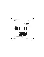
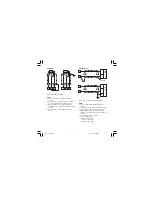
CONNECTION DIAGRAMS
Connections are to be made with the instrument
housing installed in its proper location.
Fig. 3 .A
REAR TERMINAL BLOCK
A) MEASURING INPUTS
NOTE
: Any external components (like zener
barriers etc.) connected between sensor and
input terminals may cause errors in measurement
due to excessive and/or not balanced line
resistance or possible leakage currents.
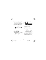
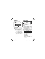
TC INPUT
Fig. 4
NOTE
:
1) Don’t run input wires together with power
cables.
2) For TC wiring use proper compensating cable
preferable shielded.
3) when a shielded cable is used, it should be
connected at one point only.
9
+
_
Shield
9
+
_
Shield
10
10
1604-7-1-AB.p65
5/16/00, 10:50 AM
3


