Manual Operation
3-31
3.3.3.4
Setting Series Parameters
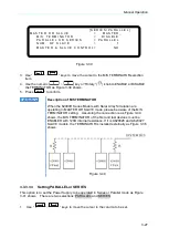
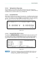
When the software communication and hardware settings for series are completed, the
settings of following windows are introduced in the sections underneath - (1) MAIN PAGE, (2)
SYSTEM SETUP, (3) OUTPUT SETUP and (4) PROTECTION.
3.3.3.4.1
Setting MAIN PAGE
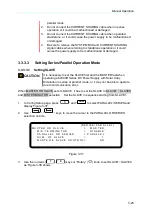
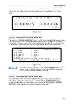
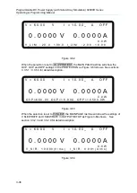
MAIN PAGE is mainly used to set voltage (V) and current (I). The difference between single
unit and series operation is that the voltage set will increase following the number connected
in series. The voltage set is indicated by
ΣV for easy identification. When set to MASTER,
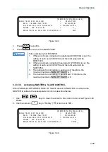
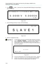
MST will appear at the window’s upper right corner as Figure 3-48 shows below.
∑ V = 6 0. 0 0 _ V I = 1 0. 0 0 A M S T O F F
0 . 0 0 0 0 V 0 . 0 0 0 0 A
0 . 0 W
Figure 3-48
3.3.3.4.2
Setting SYSTEM SETUP for Series
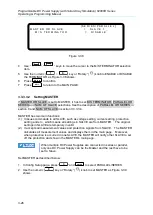
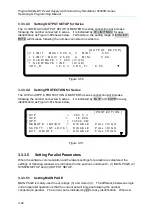
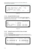
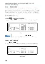
The operation of POWER ON STATUS in SYSTEM SETUP for series is the same as single
unit; only the output voltage will increase following the number of machines set in series.
For example if there are 2 sets of 62150H-600S in series, the maximum output voltage can
be set is 1200V, and the maximum output current is 25A as Figure 3-49 shows below:
[S Y S T E M S E T U P]
A P G V S E T =
N O N E
A P G I S E T
=
N O N E
A P G V M E A S
= N O N E
A P G I M E A S
= N O N E
B U Z Z E R
= O N
P O W E R O N S T A T E S = U S E R D E F I N I T I O N _
∑ V = 1 2 0 0 . 0 0 V I =2 5 . 0 0 0 A O U T P U T = O F F
Figure 3-49
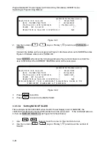
It will return to single unit mode once the POWER ON STATUS is set in
series mode. The POWER ON STATUS sets the output voltage and
current to 0 and OUTPUT to OFF automatically.

