background image

   Printed circuit boards and sensors

HS Series D13 Service Manual

99

020-000892-03 Rev. 1 (12-2019)

Removing the thermal sensor board

To remove the thermal sensor board, complete the following steps.

1. Remove the top cover.

See 

Removing the top cover

 on page 64.

2. Remove the main board top shielding.

See 

Replacing the main board and media board

 on page 99.

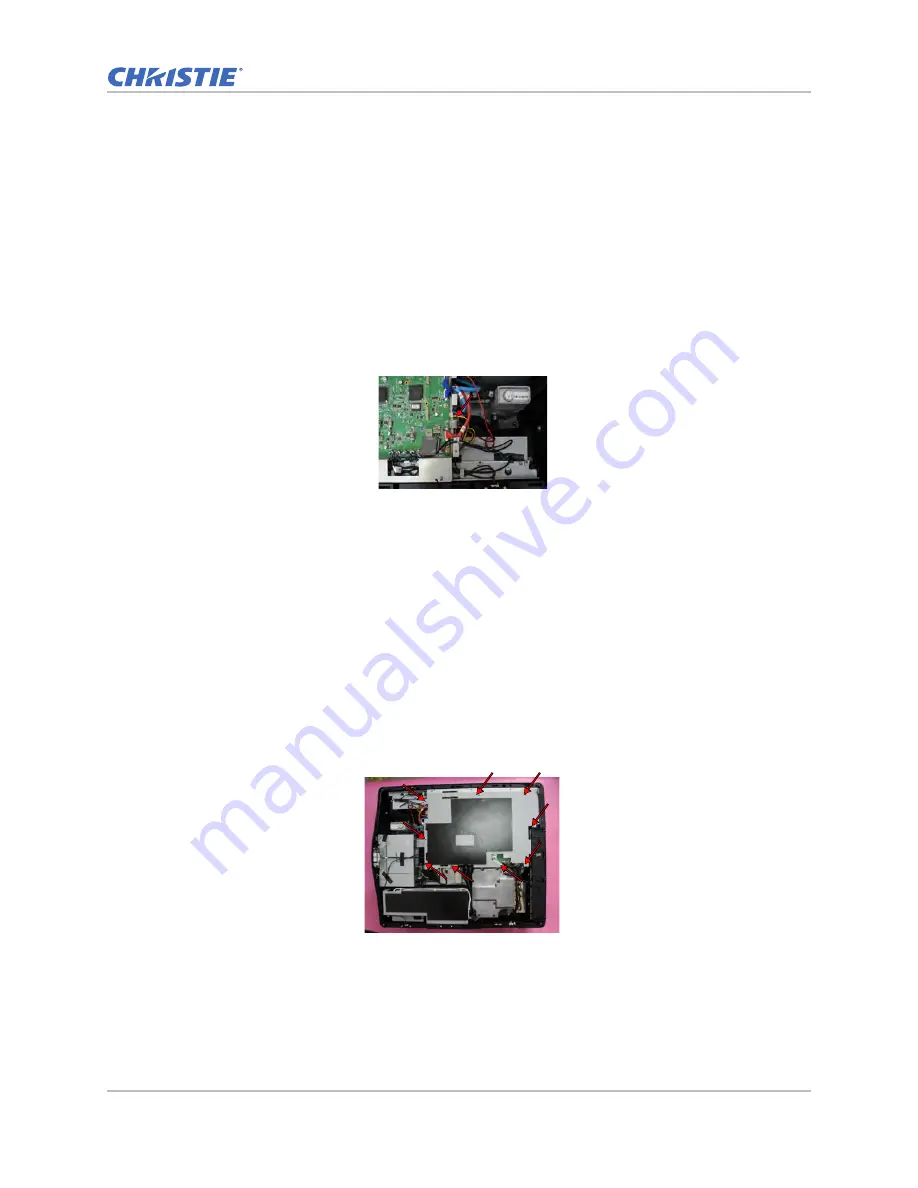
3. On the main board, unplug the thermal sensor connector. 

4. On the main board bottom shielding, remove the one M3 screws with a Phillips #1 screwdriver. 

5. Remove the thermal sensor board.

6. Replace the thermal sensor board.

7. To re-install, follow these steps in reverse order.

Replacing the main board and media board

To remove the main board, complete the following steps.

1. Remove the top cover.

See 

Removing the top cover

 on page 64.

2. To remove the main board top shielding, remove the nine screws with a Phillips #1 screwdriver.

Содержание D13HD-HS

Страница 1: ...HS Series D13WU HS D13HD HS Service Manual 020 000892 03...

Страница 2: ...ved by Christie for such use f Except where the product is designed for outdoor use problems or damage caused by use of the product outdoors unless such product is protected from precipitation or othe...

Страница 3: ...1 Servicing live equipment 11 Safety and warning guidelines 12 Laser safety warnings 13 Light intensity hazard distance 14 Maintenance and cleaning 15 Guidelines for cleaning 15 Maintaining the coolin...

Страница 4: ...Running a DVI port performance test 32 Running a 3G SDI port performance test 33 Running a 3D SYNC out port performance test 33 Running a remote port performance test 34 Running a USB A port performan...

Страница 5: ...fy the network connection 59 Parts and module replacement 60 Maintenance prerequisites 60 Tools required for service 60 Index of parts and modules 61 Projector covers and feet 64 Removing the top cove...

Страница 6: ...the main power supply 90 Removing the top cover interlock switch 91 Removing the AC inlet 92 Removing the thermal switch 94 Replacing the TEC module 95 Printed circuit boards and sensors 97 Replacing...

Страница 7: ...s are affected Christie D13HD HS Christie D13WU HS Site requirements To safely install and operate the projector the installation location must have restricted access for authorized personnel only and...

Страница 8: ...er input Selected AC inlet Projector behavior Applicable regions 1 100 to 120V 100 to 120V Full power 100 North America Japan 2 100 to 120V 200 to 240V Warning message appears on screen ECO 2 mode 50...

Страница 9: ...tion with the projector 2 Projection lens Allows automated lens control and adjustment vertical and horizontal offsets zoom and focus 3 Adjustable feet Raises or lowers the feet to level the projector...

Страница 10: ...ter 200 to 240V 3 Power button Powers the projector on or off 4 Kensington lock Secures the projector to counter tops tables and so on 5 Fuse Fuse T15A 250V 6 Cooling air vents intake Provides cooling...

Страница 11: ...ive equipment Only Christie qualified technicians who are knowledgeable about the hazards associated with hazardous voltage ultraviolet exposure and high temperatures are authorized to assemble instal...

Страница 12: ...o are trained on the precautions for the restricted access location can be granted entry to the area FIRE HAZARD Keep hands clothes and all combustible material away from the concentrated light beam o...

Страница 13: ...of the spectators eyes within the hazard distance Possibly hazardous optical radiation emitted from this product Risk group 3 This projector has a built in Class 4 laser module Never attempt to opera...

Страница 14: ...ESS HAZARD Operators must control access to the beam within the hazard distance or install the product at the height greater than or equal to 3 0 m from the floor to the beam that prevents exposure of...

Страница 15: ...sink of the combiner and handle by the housing only Wear gloves supplied Remove any contaminants with pure isopropyl alcohol and a clean lint free cloth Illumination optics system Never touch or blow...

Страница 16: ...of scratching the lens only clean the lenses if absolutely necessary A small amount of dust on the lenses has little effect on picture quality The projection lenses should be free of dust and fingerpr...

Страница 17: ...on Cotton swabs with wooden stems only Lens cleaning cloth microfiber Warning If not avoided the following could result in death or serious injury FIRE AND SHOCK HAZARD Use only the attachments access...

Страница 18: ...fingers use the tension in the folded cloth itself to collect dust 3 If significant dust is still bound to the surface dampen a clean microfiber cloth with coated optics cleaner solution damp not dri...

Страница 19: ...ipped Component S Video Composite and HDMI HDTV Source 480P 720P 1080P Quantum Data 802B or CHROMA2327 Color Video Signal and Pattern Generator Chroma meter CL200 HD BaseT extender CH 506TX Voltage te...

Страница 20: ...r Performing a factory reset Erase all end user settings and restore the default on screen display setting 1 Enter Service mode See Entering Service mode on page 20 2 Select Factory Reset Test inspect...

Страница 21: ...ys to minimize video flicker 2 Select Menu Size Position Network test x x HDBaseT function test x Warning If not avoided the following could result in death or serious injury Do not stare into beam wh...

Страница 22: ...ight engine To perform the auto brightness constant ABC calibration complete the steps below Warning If not avoided the following could result in death or serious injury Do not stare into beam when th...

Страница 23: ...sor calibration again until the display shows Light sensor calibration has been done 7 After completing the adjustment tighten the screw on the side of the gear as indicated by the arrow Calibrating t...

Страница 24: ...ADC Calibration Help After a few seconds the ADC calibration status changes from Doing to Done Performing a video calibration To perform the video calibration complete the steps below Warning If not a...

Страница 25: ...Project an image of 100 inch in a dark environment 2 Lux 4 Enter Service mode See Entering Service mode on page 20 5 Click Test Pattern select the White Screen test pattern 2 Test signal D13HD HS Anal...

Страница 26: ...alance over 50 cm perform adjusting the focus Adjusting the back focus To set up for the back focus adjustment follow the steps below 1 Use the PC to project a Full Screen test pattern 2 Adjust the le...

Страница 27: ...ustment on HS Series projectors is opposite to the bore sight adjustment on E G and GS Series projectors Adjust the three set screws with a M4 Allen key to make the image clear crisp and sharp 1 To ad...

Страница 28: ...n the clockwise direction back to their factory default setting c Check that the alignment of the set screws matches what is shown in the image below Adjusting the phosphor index After replacing main...

Страница 29: ...appear smooth b Record the a index value c Adjust the index downwards until blue does not appear smooth d Record the b index value e Set the index value to a b 2 Adjusting the color index After repla...

Страница 30: ...ther color levels are not taken into account a Adjust the index upwards until blue does not appear smooth b Record the a index value c Adjust the index downwards until blue does not appear smooth d Re...

Страница 31: ...d or I O board see Replacing the main board and media board on page 99 and Removing the I O board on page 104 Running a VGA port performance test To perform the VGA port performance test complete the...

Страница 32: ...deo generator using a DVI cable 2 Switch the signal source to DVI The image of video generator is projected ID Part name Description 1 Test equipment DVD player with HDMI output set to 16 9 2 Test sig...

Страница 33: ...onnect the projector and RF emitter using a BNC cable 2 Wear the 3D RF glasses 3 Switch the signal source to 3D SYNC The 3D image is projected ID Part name Description 1 Test equipment DVD player 2 Te...

Страница 34: ...eps 1 Connect a U disk to the projector over the USB A port 2 Switch the signal source to Card reader The data of U disk is projected ID Part name Description 1 Test equipment Remote controller 2 Test...

Страница 35: ...ing the main board and media board on page 99 1 On the IR remote keypad press Menu Input Switching PIP Menu 2 Set PIP PBP Enable to On 3 Ensure each item is functioning normally Performing a network f...

Страница 36: ...col TCP IP d Click Properties e Set the IP Address to 192 168 0 240 f Set the Subnet Mask to 255 255 255 0 The Host ID 192 168 0 XXX of the PC IP Address must be different from the projector IP addres...

Страница 37: ...default The Subnet Mask 255 255 255 0 default 2 In Network settings set the projector IP address See Performing a network function test on the network port on page 35 3 Read the projector information...

Страница 38: ...ox Version 46 or higher is required Safari Not supported To perform the wireless function test complete the following steps 1 Connect to the wireless SSID a Insert the WiFi USB dongle 1DWUSB BGN into...

Страница 39: ...Christie Presenter b Click OK c Click Next d Click I Agree e Click Next f Click Next g Enter the name and click Next h Click Install i Select I want to manually reboot later j Click Finish 4 Perform w...

Страница 40: ...s shall expand to full screen size using the on screen display Horizontal and Vertical Size controls 4 Display data channel The purpose of the DDC test is to verify the DDC DDC1 DDC2B operation of the...

Страница 41: ...HDD sleep timer to greater than two hours The firmware upgrade procedure for D13WU HS is the same as D13HD HS D13HD HS is used as the example ID Equipment needed 1 Software OPFU One package firmware u...

Страница 42: ...ogram file from the Christie website www christiedigital com 2 Unzip the file to the desktop and open the folder created 3 Execute Wizard OPFU EXE Upgrading the firmware To complete the firmware upgra...

Страница 43: ...rce message is displayed on the bottom left of the projected image click Next 6 Connect the projector to the computer with a RJ45 cable a Set the Default Gateway and Subnet Mask of the computer to mat...

Страница 44: ...03 Rev 1 12 2019 7 On the Prepare to Update Projector tab select your projector model name Click Next 8 Choose the firmware version that you want to upgrade to click Next The firmware upgrade procedur...

Страница 45: ...ode and select Projector Info 10 Click Exit Performing a firmware recovery To perform a firmware recovery complete the following steps 1 Repeat steps 1 through 9 in the firmware upgrade process See Up...

Страница 46: ...are recovery did not work complete the following steps to recover the local area network 1 Connect AC power and turn the power switch to on position 2 Press the UP key followed by the POWER key 3 When...

Страница 47: ...0 8 To start the firmware upgrade click Flash The upgrade takes about eight minutes The screen appears frozen during this time Do not force a shutdown Programming is completed once the LAN firmware u...

Страница 48: ...blem exists with the projector that does not cause it to shut down Examples include filter needs changing one of the pumps is damaged or a fan is operating at full speed due to over temperature of the...

Страница 49: ...er to verify image performance No Is the IR remote keypad working Refer to verify the IR remote keypad operation No No fault found Yes No End Is the network connection functioning Refer to verify the...

Страница 50: ...H SRZHU VRXUFH V WKH SRZHU VRXUFH SURYLGLQJ YROWDJH HV 1R 3URSHUO FRQQHFW WKH SRZHU FRUG DW 7KH SURMHFWRU DQG SRZHU VRXUFH 6XSSO YROWDJH 9 RU 9 V WKH LQWHUORFN VZLWFK FORVHG HV QVXUH WKH LQWHUORFN VZL...

Страница 51: ...2 Measure the voltage of J2 pin5 6 on the main board Is the output 5V Measure the voltage of J1 on the main board pins 1 11 Is the output 12V Replace the LVPS Measure the voltages of J46 J48 pin 2 on...

Страница 52: ...n J68 J71 J75 J77 J79 J83 pin1 on the main boar is the output 12V 10 Replace the main board Yes Is the projector functioning as expected and is the status LED green Replace the thermal switch No Measu...

Страница 53: ...ion turned on Show Enter PIN dialog Box on the screen Yes Is the PIN correct Yes Start No Turn off the unit then Hold the power Button and press the Enter button at the same time PIN will be reset to...

Страница 54: ...creen displaying white Replace the DMD board Replace the main board Ensure that the signal cable and signal source are working Does PC image show on the screen Replace the Main board Yes Yes No Yes No...

Страница 55: ...index adjust procedure Does the color appear normal Yes No No 1 2 1 3 Replace the main board Does the color appear normal Replace the color wheel module No No Does the Video image show on the screen E...

Страница 56: ...the socket and LVDS bus to DMD gold finger and this need to be done in a clean room Is there noise in the image Check the signal cable and signal source connection and functionality Adjust the pixel...

Страница 57: ...shift working correctly Replace the horizontal lens motor Is the vertical lens shift working correctly Replace the vertical lens motor Replace the light engine Yes Yes Replace the light engine Yes Is...

Страница 58: ...the unit powered on Is the unit power on Check the IR board connections in the remote Does the OSD menu show up on screen Press the menu button on the IR remote keypad No No No Fault Found Yes Plug i...

Страница 59: ...e Network settings of the unit correct Is the Network functioning correctly No Fault Found End Is the Internet source on the PC working Replace the Lan cable Use an alternate PC Change the Network set...

Страница 60: ...or perform the following tasks Always power down and disengage all power sources to the projector prior to servicing Follow all service safety guidelines For detailed breakdown of serviceable modules...

Страница 61: ...tronics Fuse 15A 250V 5 20 003 005675 XX Fuse 20A 250V 5 20 003 005676 XX Motor stepping DC 12V 003 003483 XX Top cover interlock switch 003 005621 XX Filter switch 003 005619 XX AC inlet switch 003 0...

Страница 62: ...X Main printed circuit board D13WU HS 003 005679 XX Mechanical Front cover black 003 005642 XX Cable cover 003 005631 XX Bottom cover black 003 005632 XX Keypad cover black 003 005628 XX Keypad button...

Страница 63: ...3 Rev 1 12 2019 Optional lens TR 1 2 1 5 140 109101 XX STD lens TR 1 5 2 0 140 110103 XX Optional lens TR 2 0 4 0 140 111104 XX Optional lens TR 4 0 7 2 140 116109 XX Optional lens TR 0 84 1 02 140 11...

Страница 64: ...omponents 1 On the rear cover side remove the three captive screws with a Phillips 1 screwdriver 2 Slide the top cover towards the front of the projector and lift it 3 Remove the top cover 4 If requir...

Страница 65: ...ver module from projector 6 Remove the rear IR sensor board See Replacing the rear IR sensor board on page 98 7 Remove fans 1 2 and 3 See Replacing fans 1 2 and 3 on page 71 8 Transfer the rear IR sen...

Страница 66: ...Phillips 1 screwdriver securing the front cover module 8 Remove the front cover from the projector 9 Remove the front IR sensor board See Replacing the front IR sensor board on page 98 10 Transfer the...

Страница 67: ...attached to the cord of the filter R switch 7 Remove the filter R switch See Removing the filter R switch on page 85 8 Transfer the filter R switch to the new right side cover 9 If required replace th...

Страница 68: ...12 To re install follow these steps in reverse order Removing the bottom cover To remove the bottom cover complete the following steps 1 Remove all covers from the projector See Removing the top cove...

Страница 69: ...he AC inlet See Removing the AC inlet on page 92 11 Remove the elevator feet from the bottom cover See Replacing a projector s foot on page 69 12 Remove the two M3 screws with a Phillips 1 screwdriver...

Страница 70: ...board on page 99 4 Remove the rear cover See Removing the rear cover on page 64 5 Remove the I O board See Removing the I O board on page 104 6 Remove the front cover See Removing the front cover on...

Страница 71: ...ents When replacing fans ensure you confirm the fan direction for airflow The correct orientation of the fan also ensures that the fan harness reaches the connector Replacing fans 1 2 and 3 The fans 1...

Страница 72: ...bber 8 Replace the affected fan 9 To re install follow these steps in reverse order Replacing fans 4 5 6 and 7 The fans 4 5 6 and 7 draw the air into the projector and provides exhaust cooling for the...

Страница 73: ...ng fan 8 The fan 8 provides air cooling for power supply module 1 Remove the top cover See Removing the top cover on page 64 2 Remove the main board and main board bottom shielding See Replacing the m...

Страница 74: ...follow these steps in reverse order Replacing fan 11 The fan 11 provides the intake air cooling for the color wheel assemblies 1 Remove the top cover from the projector See Removing the top cover on p...

Страница 75: ...8 Remove the laser driver board See Replacing the blue1 and 2 laser driver board on page 105 Replacing the red laser driver board on page 106 9 Remove the complete light engine See Replacing the compl...

Страница 76: ...o center the lens press the Lens Horizontal or Lens Vertical button d Press Enter 2 Turn the projector off and disconnect it from AC power 3 Remove the lens a Use an M3 Allen key to release the screw...

Страница 77: ...and main board bottom shielding See Replacing the main board and media board on page 99 3 Remove the rear cover See Removing the rear cover on page 64 4 Remove the I O board See Removing the I O boar...

Страница 78: ...ld the light engine so to avoid any shifting or misalignment See Replacing the light engine on page 82 13 To re install follow these steps in reverse order Replacing the color wheel To remove the colo...

Страница 79: ...er 5 To release the color wheel module remove the three M3 screws with a Phillips 1 screwdriver 6 Replace the color wheel 7 To re install follow these steps in reverse order Replacing the combiner mod...

Страница 80: ...left side cover on page 67 7 Remove the power supply module from the projector See Replacing the DC 12V power supply on page 87 8 Remove the laser driver board See Replacing the blue1 and 2 laser dri...

Страница 81: ...n page 64 2 Remove the main board and main board bottom shielding See Replacing the main board and media board on page 99 3 Remove the rear cover See Removing the rear cover on page 64 4 Remove the I...

Страница 82: ...ule on page 95 13 Remove the DMD board See Replacing the DMD board on page 109 14 Take out the DMD module from light engine 15 Release the DMD socket securing the DMD 16 Replace the DMD When replacing...

Страница 83: ...placing the blue1 and 2 laser driver board on page 105 Replacing the red laser driver board on page 106 9 Remove the complete light engine See Replacing the complete light engine on page 77 10 Remove...

Страница 84: ...wer on 1 Turn off the projector 2 Choose the 100V or 220V fuse by sliding the AC cover to the right or to the left 3 Remove the screw on the fuse 4 Release the fuse and replace the new one 5 To re ins...

Страница 85: ...lips 6 Separate the filter L switch and hold cover 7 Replace the filter L switch 8 To re install follow these steps in reverse order Removing the filter R switch To remove the filter R switch complete...

Страница 86: ...nd media board on page 99 3 On the main board unplug the AC detect connector 4 Remove the rear cover See Removing the rear cover on page 64 5 Remove the front cover See Removing the front cover on pag...

Страница 87: ...ake out the pump and radiator module 7 Replace the pump and radiator module 8 To re install follow these steps in reverse order Replacing the DC 12V power supply To remove the DC 12V power supply comp...

Страница 88: ...side cover on page 67 6 Loosen the five M3 captive screws with a Phillips 1 screwdriver securing the power supply module 7 Remove the thermal switch harnesses from the clips 8 Unplug the thermal switc...

Страница 89: ...river securing the shielding cover on the left of the power supply 14 Remove the top cover interlock switch harnesses from the clips 15 Unplug the main power supply to DC 12 power supply harness conne...

Страница 90: ...laser driver 1 Remove the top cover See Removing the top cover on page 64 2 Remove the main board and main board bottom shielding See Replacing the main board and media board on page 99 3 Remove the r...

Страница 91: ...Replace the main power supply 13 To re install follow these steps in reverse order Removing the top cover interlock switch The top cover interlock switch prevents the projector from operating when th...

Страница 92: ...ace the interlock switch 9 To re install follow these steps in reverse order Removing the AC inlet To remove the AC inlet complete the following steps 1 Remove the top cover See Removing the top cover...

Страница 93: ...nlet to the power supply connectors 8 Remove the insulation covers 9 Unplug the positive pole of AC inlet 10 Remove the switch of AC inlet from the bracket 11 Remove the corresponding M3 ground screw...

Страница 94: ...board bottom shielding See Replacing the main board and media board on page 99 3 Remove the I O board See Removing the I O board on page 104 4 Remove the rear cover See Removing the rear cover on page...

Страница 95: ...move the top cover See Removing the top cover on page 64 2 Remove the main board and main board bottom shielding See Replacing the main board and media board on page 99 3 Remove the rear cover See Rem...

Страница 96: ...iver securing the DMD thermal module 10 Remove the two M2 6 screws with a Phillips Jewelers screwdriver securing the TEC module 11 Separate the TEC module and plastic cover 12 Replace the TEC module W...

Страница 97: ...h as temperature light and communication into electrical signals Replacing the LED board To remove the LED board complete the following steps 1 Remove the top cover See Removing the top cover on page...

Страница 98: ...ug the rear IR connector 4 Remove the rear IR sensor board from the hook of rear cover 5 Replace the rear IR sensor board 6 To re install follow these steps in reverse order Replacing the front IR sen...

Страница 99: ...ard on page 99 3 On the main board unplug the thermal sensor connector 4 On the main board bottom shielding remove the one M3 screws with a Phillips 1 screwdriver 5 Remove the thermal sensor board 6 R...

Страница 100: ...3 M3 screws with a Phillips 1 screwdriver 4 On the top side of the main board disconnect the 23 connectors indicated by the labels A X in the image below 5 Disconnect the five connectors on the bottom...

Страница 101: ...black wire tube three pin E J50 KEYPAD White connector and black wire tube 30 pin F J82 COMBINER White connector 20 pin G J79 FAN11 Composed of red black yellow and white wires a white connector and...

Страница 102: ...e connector and a black wire tube six pin P J47 DRIVER BD B1 Composed of red and blue wires a white connector and a blue wire tube 30 pin Q J46 DRIVER BD B2 Composed of red and blue wires a white conn...

Страница 103: ...ocket driver 12 Remove the I O cover 13 Flip the main board over to access the media board 14 To remove the media board remove the three M3 screws with a Phillips 1 screwdriver and lift off the media...

Страница 104: ...top cover on page 64 2 Remove the main board and main board bottom shielding See Replacing the main board and media board on page 99 3 Remove the rear cover See Removing the rear cover on page 64 4 R...

Страница 105: ...steps in reverse order Replacing the blue1 and 2 laser driver board To remove the blue 1 and 2 laser driver board complete the following steps 1 Remove the top cover See Removing the top cover on page...

Страница 106: ...river 6 Replace the laser driver board 7 Transfer the heatsink to the new laser driver board 8 To re install follow these steps in reverse order Replacing the red laser driver board To remove the red...

Страница 107: ...m the heatsink remove the four M3 screws with a Phillips 1 screwdriver 6 Replace the red laser driver board 7 Transfer the heatsink to the new laser driver board 8 To re install follow these steps in...

Страница 108: ...screwdriver 4 Take out the keyapd and keypad board from the projector 5 Unplug the two connectors 6 Remove the six M3 screws with a Phillips 1 screwdriver securing the keypad board 7 To remove the key...

Страница 109: ...e photo sensor board 4 To re install follow these steps in reverse order Replacing the DMD board To remove the DMD board complete the following steps 1 Remove the complete light engine See Replacing t...

Страница 110: ...circuit boards and sensors HS Series D13 Service Manual 110 020 000892 03 Rev 1 12 2019 7 Remove the DMD mylar from the DMD board 8 Replace the DMD board 9 To re install follow these steps in reverse...

Страница 111: ...ic of South Africa ph 27 0 11 510 0094 Korea Seoul ph 82 2 702 1601 Japan Tokyo ph 81 3 3599 7481 India ph 91 080 6708 9999 Germany ph 49 2161 664540 France ph 33 0 1 41 21 44 04 Russian Federation an...

Страница 112: ......

Отзывы: