


2-31
Safety and Operations
INDICATOR LAMP
When the Fireboy system
is activated the engine and the blower
will be shut down automatically.
Check the indicator lamp.
♦
The indicator lamp is designed to
monitor the state of the fire
extinguisher when the ignition
key is
ON
.
♦
A
GLOWING GREEN
light
indicates the system is
CHARGED
.
♦
A
NON-GLOWING GREEN
LIGHT
indicates the system is
DISCHARGED
.
The engine compartment blowers are
required to have a ground connection
to be connected to the Fireboy system.
Failure to connect a power ventila-
tion system impedes the operation
of the fire extinguisher and may
prevent fire extinguishment.
NOTICE:
NOTICE:
PULL PIN
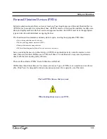
Operation of the Fireboy Fire Extinguisher
♦
Automatic actuation of a Fireboy fire extinguisher occurs
at 175 degrees F. and is entirely dependent on the intensity
of the fire.
♦
Signs of actuation:
1. A loud sound similar to small arms fire.
2. A loud sound of rushing air.
3. An extinguished indicator lamp.
4. A stalled engine.
♦
When Actuation occurs:
1. Immediately shutdown all engines, powered
ventilation, and electrical systems.
2. Do not open the engine compartment.
♦
After actuation occurs:
1. Before inspecting for damage, allow the agent to
“soak” the compartment for at least 15 minutes and
wait for hot metals or fuels to cool.
2. Have approved portable extinguishers in hand and
ready for use.
3. Do not breathe fumes or vapors caused by the fire.
They are hazardous and toxic.
With the “S” hook in
place, and the cable end
retaining clip
NOT
installed, any pull
on the cable exceeding 20 pounds
will actuate the release mechanism.
The cable should never be installed
or removed without the cylinder
securely fastened in its mounting
brackets.
CAUTION:
Figure 2.6
Figure 2.7
Figure 2.8
Содержание 2014 36 RH Corsair
Страница 19: ...Introduction 36 RH Corsair B...
Страница 23: ...Safety and Operations...
Страница 57: ...2 36 Safety and Operations...
Страница 88: ...Figure 3 26 Fluid Tank Sensor 3 30 Systems...
Страница 113: ...Entertainment and Convenience 3 55 Systems Figure 3 48 Cockpit Refrigerator Figure 3 47 Wet Bar and Sink...
Страница 115: ...Care and Cleaning 3 57 Systems Marine Tops And Covers Care And Cleaning...
Страница 116: ...Care and Cleaning Figure 3 51 Canvas Top 3 58 Systems...
Страница 118: ...Care and Cleaning 3 60 Systems Maintenance and Cleaning Of Stainless Steel...
Страница 121: ...3 63 Systems Grey Water Systems Figure 3 56...
Страница 126: ...Figure 3 70 Figure 3 68 3 68 Systems Figure 3 66 Figure 3 67 Figure 3 69 Cockpit Table...
Страница 134: ...3 76...
Страница 149: ...Coast Guard Accident Report B 2 Appendix B...
Страница 150: ...Coast Guard Accident Report B 3 Appendix B...
Страница 151: ...B 4 Appendix B Coast Guard Accident Report...
Страница 152: ...Coast Guard Accident Report B 5 Appendix B...
Страница 154: ...C 2 Appendix C SPECIAL NOTICE TO MARINERS Float Plan...
Страница 155: ...Appendix C C 3 Float Plan...
Страница 158: ...Navigational Aids D 3 Appendix D...
Страница 159: ...Lateral Aids D 4 Appendix D...
Страница 161: ...Maintenance Log Forms E 2 Appendix E...
Страница 162: ...Maintenance Log Forms E 3 Appendix E...
Страница 163: ...Glossary Of Boating Terminology Appendix F F 1...
Страница 164: ...F 2...
Страница 165: ...F 3...
Страница 166: ...F 4...
Страница 167: ...F 5...
Страница 168: ...F 6...
Страница 169: ...5 7 F 7...
Страница 170: ...F 8...
Страница 171: ...F 8...
Страница 172: ...G 1 Figure 4 21...
Страница 173: ...G 2 Figure 4 22...
Страница 174: ...G 3 Figure 4 23...
Страница 175: ...G 4 Figure 4 24...
Страница 176: ...G 5...
Страница 177: ...G 6 Figure 4 26...
Страница 178: ...G 7 Figure 4 27...
Страница 179: ...G 8 Figure 4 28...
Страница 180: ...Figure 4 29 G 9...


