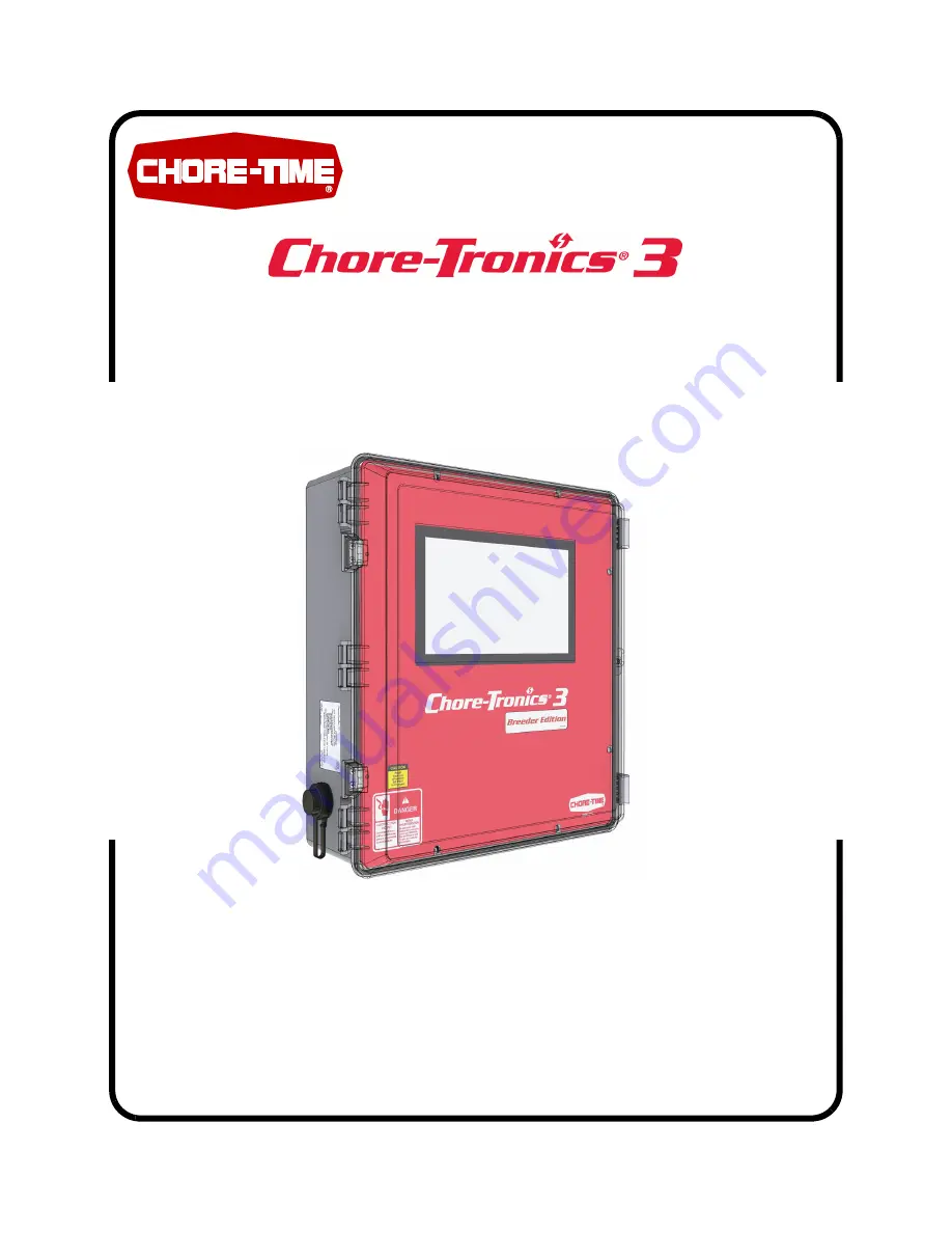
Chore-Time Tronics 3 Скачать руководство пользователя страница 1

Chore-Tronics

®

 3 Breeder Edition Control

For additional parts and information, contact your nearest Chore-Time distributor or representative.

Find your nearest distributor at: www.choretime.com/contacts

MT2484A

September 2021

Installation and Operators Manual

Installation and Operators Manual

Содержание Tronics 3

Страница 1: ...additional parts and information contact your nearest Chore Time distributor or representative Find your nearest distributor at www choretime com contacts MT2484A September 2021 Installation and Operators Manual Installation and Operators Manual ...

Страница 2: ... the exclusion or limitation of such damages so these limitations and exclusions may not apply to you This warranty gives the original purchaser specific legal rights You may also have other rights based upon your specific jurisdiction Compliance with federal state and local rules which apply to the location installation and use of the Product are the responsibility of the original purchaser and C...

Страница 3: ...ump Scale 12 Mechanical Scale 13 Egg Counters 14 Outputs 15 Clocks Tab 15 Note Four output relays can be assigned to each Clock 15 Feeding System Matrix 18 Feeding System Setup Examples 18 Output Setup Egg Room Relative Humidity and Temp Cooler and Humidity 21 Clocks Setup 22 Management Screens 26 Mortality 26 Feed 27 Inventory 28 Egg 28 History Screens 30 Environment 30 Production 30 Wiring 32 Bi...

Страница 4: ...Contents continued Topic Page 4 MT2484A Special Functions 38 Tunnel Fan at Feeding 38 Charts 39 ...

Страница 5: ...sing the equipment for purposes other than specified in this manual may cause personal injury and or damage to the equipment Follow Safety Instructions Carefully read all safety messages in this manual and on your equipment safety signs Follow recommended precautions and safe operating practices Keep safety signs in good condition Replace missing or damaged safety signs Decal Descriptions DANGER E...

Страница 6: ...ure sensor 4 20 mA Relative Humidity Sensor 0 10 volts Potentiometer Natural Ventilation Analog Inputs Egg Room Relative Humidity Sensor 1 In the Setup Analog Type Number screen check Egg Room Humidity 2 See Relative Humidity Sensor RH Wiring on page 36 1 Assign the Egg Room Relative Humidity Sensor to the Analog input you connected the sensor to Control Setup 2 ...

Страница 7: ...oom Temperature Sensor 1 In the Setup Analog Type Number screen check Egg Room Temperature 2 See Temperature Sensor Wiring on page 36 Temperature Sensor Analog Input Assignment 1 Assign the Egg Room Temperature Sensor to the Analog Input where you connected the Sensor 1 ...

Страница 8: ... the Load Cell button 3 From the Board dropdown menu select the device being used for the Load cell input LCC or ILM Note ILM is how the SJB is identified in the CT3 Control 4 From the Input dropdown select the Analog input where the board is connected 5 If a Bin Lid switch is used enter the Digital in 6 Select the Control Tab and select the Bin Size from the dropdown 3 4 5 6 ...

Страница 9: ...he ON position to allow the ZERO to be tracked by the house controls 4 Set S4 to the ON position to provide a 2mV V at full scale instead 5 Bin D must be enabled on the Bin Trac Indicator when BinTrac Monitor is connected to BinTrac HouseLink HL 10P HL 10P LV 6 Refer to the BinTrac Installation and Operation Manual HouseLINK HL 10P HL 10P LV on how to make these settings 7 Once the unit is wired a...

Страница 10: ...take you to the Zero Calibration screen 3 Make sure the calibration numbers are steady Select OK If the calibration is accepted the screen will change to Weight Calibration of Scale screen 4 At the HouseLink HL 10P LV press the TEST button one time for the 2mV V output setting which represents a full bin weight reading 5 At the Chore Tronic s 3 in the Weight Calibration Scale screen enter the capa...

Страница 11: ...CT 3 IO terminals to the SJB IO net terminals Calibration 1 Go to the Setup Analog Inputs Load Cell Screen and Select Calibrate 2 With no feed in the Bin select the OK Button If there is no error then continue 3 At the Chore Tronic s 3 in the Weight Calibration Scale screen enter the known weight in the Bin and the units wanted from the dropdown Example shows 500 lb 3 2 ...

Страница 12: ...tch is connected 4 Enter the Board Input Name the Scale Units per pulse and Units 5 If one or more Feed Scales are used they need to be connected to one of the Digital DI Inputs on the IO board using Twisted Pair Wire Connect the switch located on the side of the Feed Scale to the IO Board using the blue and brown wires See Figure 1 See manual MT1811 for more information on the Dump Scale 2 2 2 4 ...

Страница 13: ...al Inputs Type numbers Screen put a Check mark in the Mechanical Scale box 2 Select the Mechanical Scale button 3 From the drop downs select the Board and Input 4 The Status column shows if the switch is activated or not 5 See Wiring Chore Tronics Control and Weigh matic Scale for wiring information 3 3 ...

Страница 14: ...Egg Counter Button 3 From the drop downs select the Board and Input 4 You can Add or Remove Counters 5 Up to five sets of Counters can be added Each Set consists of two Counters and one Switch Switch is used to kept track of Run Times and to tell the CT 3 to start counting egg when the belts start Examples 2 4 3 Example House with Single Belt Collectors One Set of Counters Example House with Two D...

Страница 15: ...igned to each Clock Female Feed Clock 1 Go to the Setup Outputs Clock Screen and Select Female Feed 2 Rename if needed Assign Relays as needed 3 Select the Control Tab 4 A check in the Disable All Female Feed Delivery At Max Runtime box will turn off the Female Fill when Feeder run time is met 5 A check in the Stop feed when preset is for box s will turn off the Female feeder when the Preset curre...

Страница 16: ... up for the Male Water Clock is the same as for the Female Water Clock Feeder Fill Clock In the Setup Outputs Clock Feeder Fill Screen enter 1 The Relay or Relays from the dropdown 2 Select the Scale type from the dropdown 3 Select the scale number from the dropdown 4 Rename if needed Note Follow the same steps to setup all Feeder Fill Clocks Caution Do not allow Weigh Fill and Feeder Fill Times t...

Страница 17: ...A 17 Feed Winch Clock Male Feeder Winch In the Setup Outputs Clock Feed Winch Screen enter 1 The Relay or Relays from the dropdown 2 Rename if needed Light Clock Spare Clock and PDS Clock See the Chore Tronics Manual to set up the Light Spare and PDS Clocks 1 2 ...

Страница 18: ...the user to setup six different Feeding Systems Clocks that are to be used in a specific Feeding System are entered in the Matrix Important It is very important to assign both the Male Female choice as well as the line number in this Screen Failure to do so could cause Clocks to follow the wrong schedule Feeding System Setup Examples The examples to follow show how the Clocks are assigned and how ...

Страница 19: ...Chore Tronics 3 Breeder Edition Control Control Setup MT2484A 19 S Supply Bin W Weigh Bin S S W W S S Supply Bin W Weigh Bin w S S Supply Bin W Weigh Bin S w S Supply Bin W Weigh Bin ...

Страница 20: ...Control Setup Chore Tronics 3 Breeder Edition Control 20 MT2484A S S Females Feeder Fill 1 S Supply Bin W Weigh Bin Males Feeder Fill 2 S Supply Bin W Weigh Bin S w S w S w Female Female Male ...

Страница 21: ...tputs Ventilation screen select the Egg Room button 3 Enter the Relay numbers for the Cool Heat and Humidifier Outputs and Temperatures Screen Egg Room Tab 1 This column lists the on temperatures of the outputs listed 2 This column lists the off temperatures for the cool and heat outputs of the Egg Room only 3 Set Desired target temperature of the Egg Room 4 Humidifier Humidity range at which the ...

Страница 22: ... The first line of the schedule indicates the Feed and Non Feed days of the current week The second line of the schedule indicates the Feed and Non Feed days of the next week The schedule will be repeated every two weeks 3 On at The time of day that an event will start 4 Off at The time of day hours minutes seconds that an event will turn off Note If Stop feed when preset is met has been setup the...

Страница 23: ...ble one schedule for feed days and one schedule for non feed days The Feed and Non Feed days are determined by the female feed clock run schedule assigned to it in the Feed System Matrix Feed System Screen Use the dropdown to select between the Feed day and the Non Feed day water clock schedules 5 Events The desired number of timed events The maximum number is 24 6 Use Curve Select On or Off from ...

Страница 24: ... Feed day 2 Fill Clocks Select the Fill Clock needed to setup 3 On at The time of day that an event will start 4 Off at The time of day hours minutes seconds that an even will run 5 Run for The total time in hours minutes seconds that the Feeder will run 6 Events The desired number of timed events The maximum number is 24 7 Use Preset From the dropdown select Yes or No A Preset is a specific amoun...

Страница 25: ...e Run For Curves 6 Curve Select the Curve number you want to use from the dropdown Note Feed Winch Clock will lower the Male Feed Line only Line must be manually raised Weigh Fill Clock The Weigh Fill Clock is used to control the Fill system that supplies feed to a Weigh bin on Load cells 1 On at The time of day that an event will start 2 Off at The time of day hours minutes seconds that an even w...

Страница 26: ...and culled then select Agreed to enter 2 Initial Housed Enter the number of Females placed 3 Partial Taken Out Enter the number of Females removed Mortality Males 1 Picked Up Enter today s dead and culled then select Agreed to enter 2 Initial Housed Enter the number of Males placed 3 Partial Taken Out Enter the number of Males removed 4 Males Spiked Males placed after initially housed 2 1 3 2 1 3 ...

Страница 27: ...Load Cells and Dump Scales 2 Feed Consumed Previous Editable from 1 to 60 minutes 3 Feed Cumulative Per Feed Per X number for birds consumed from start of the flock 4 From the dropdown select 1 100 or 1000 Birds 5 Feed Today Feed Per X number for birds consumed from midnight till current 6 From the dropdown select 1 100 or 1000 Birds 2 3 5 1 4 6 ...

Страница 28: ...ory of a Load cell scale is automatically displayed 3 For the control to display an inventory for the Mechanical and Dump scale the user has to enter all the feed deliveries This is done by entering the amount of feed delivered then selecting Agree 4 Name Edit the Name of the bin if needed Egg Total Tab This screen displays the total number of eggs collected Hand Auto count and Floor eggs 1 To dis...

Страница 29: ...lect Agreed to save Manual Counting If no egg counter is used 1 Enter the number of Hatching eggs 2 Enter the number of Culled eggs 3 Enter the number of Double Yolk eggs 4 Select Agreed to save Floor Tab 1 Enter the number of Hatching eggs 2 Enter the number of Culled eggs 3 Enter the number of Double Yolk eggs 4 Select Agreed to save 1 2 1 2 3 1 2 3 4 ...

Страница 30: ...s of the Minimum and Maximum temperature as well as the time of day of both Humidity This screen displays the last 14 days of the Minimum and Maximum Humidity as well as the time of day of both Production All the History Production screens have a 14 day screen and a 52 week screen Note Water Mortality have a 100 day history and a 52 week history ...

Страница 31: ...ls Dump Scales or Feed line Run Times History Day Week 1 Select to toggle from week to day information 2 Actual amount of Feed delivered for a given week day 3 Daily Preset for a given week day The History for Mech Scales Load Cells and Dump Scales are in the same format as the Feeder Fill The Feed Line Screen is in the same format with the exception it displays the run times of the Feed Lines if ...

Страница 32: ...one address higher than the last IO addressed used Set LCC Board Dip Switches all to Off SJB Scale Junction Box BinTrac HouseLink HL 10P ON 1 2 3 4 2 Bin S1 S2 S3 S4 D On On Off Off Bin S1 S2 S3 S4 A Off Off Off Off Bin S1 S2 S3 S4 B On Off Off Off ON 1 2 3 4 2 Bin S1 S2 S3 S4 C Off On Off Off ON 1 2 3 4 2 ON 1 2 3 4 2 Bin Trac Dip Switch Settings 24 Volt Supply 55309 ...

Страница 33: ...Chore Tronics 3 Breeder Edition Control Wiring MT2484A 33 Backup Egg Room Cooler Wiring Backup Egg Room Humidifier Wiring ...

Страница 34: ...Off On Off Off On 14 On Off Off Off On 15 Off Off Off Off On X is Dip switch in the On position If the SJB is at the end of the IO network move the IO end of the line jumper to the ON pins Red Black White Green Shield Load Cell Connect Remaining Load Cells in the same manner Maximum of 8 Loadcells LCC Board Dip Switches all in the Off position IO End of Line Jumper On Position Set th I2I Board Dip...

Страница 35: ... To Control Feeder Line Relay 2 From Control Feeder Line Relay 3 4 5 6 7 Upper Switch 8 Upper Switch C Tronics D1 Wiring 9 Lower Switch 10 Lower Switch 11 Push Button 12 Push Button External Wiring Terminal 1 1 L1 Supply 2 L2 Supply 3 Upper Switch Out Scale Wiring 4 Upper Switch Return 5 Lower Switch Return 6 Push Button Return 7 L1 Common 8 To Control Feeder Fill Relay 9 From Control Feeder Fill ...

Страница 36: ...ee Figure 25 Terminal 3 is connected to the ground terminal of the Analog Input AI being used Make sure that the Blue Jumper above the Analog Input that the RH sensor is connected to is set to U Temperature Sensor Wiring Temperature Sensor wires can be connected to any one of the Analog Inputs AI1 through AI16 of the I O board Whatever AI Inputs the Temperature Sensors are connected to make sure t...

Страница 37: ...ait XX XX Min Sec before Alarm is triggered Preset Not Met Alarm If the Preset is not met during the Feeder Fill time a Preset Not Met Warning will display in the Overview screen This is not a Full Alarm so the Alarm relay will not activate 1 The Preset amount is setup in the Feeder Fill Clock screens Current Conditions Todays Feed 1 Preset Last Reset Date and Time the Preset was reset Manual or A...

Страница 38: ...heck in the Use Tunnel Fans During Feeding Box When Feeding Begins 2 Number of Tunnel Fans to Use 3 Extra Runtime after feeding 4 If in Power ventilation will pre open Tunnel Doors to the users setting 5 If using temp control check the Use Temperature Range During Feeding box 6 Degrees above set temperature to start turning extra Tunnel Fans back on 7 Degrees below set temperature to start turning...

Страница 39: ...ns w 60 Hopper 45 00901 8 6 427 6 15 7 45 00902 12 0 597 6 18 3 45 00903 15 4 767 6 20 11 45 00904 18 8 937 6 23 7 45 00905 22 2 1107 6 26 3 45 00906 25 6 1277 6 28 11 45 00907 28 9 1442 6 31 7 12 diameter Bins w 60 Hopper 45 01201 17 8 887 5 19 5 45 01202 23 7 1186 0 22 1 45 01203 29 7 1484 4 24 9 45 01204 35 7 1782 9 27 5 45 01205 41 6 2081 3 30 1 45 01206 47 6 2379 9 32 9 45 01207 53 6 2678 3 3...

Страница 40: ...ent that is different from the authoritative CTB published English version of the manual For current product installation and operation information please contact the customer service and or technical service departments of the appropriate CTB subsidiary or division Should you observe any questionable content in any manual please notify CTB immediately in writing to CTB Legal Department P O Box 20...

Отзывы: