background image

MV1654F

Made to work.

Built to Last.

Note:  The original, authoritative version of this manual is the [English] version produced 

by CTB, Inc. or any of its subsidiaries or divisions, (hereafter collectively referred to as 

"CTB").  Subsequent changes to any manual made by any third party have not been 

reviewed nor authenticated by CTB.  Such changes may include, but are not limited to, 

translation into languages other than [English], and additions to or deletions from the 

original content.  CTB disclaims responsibility for any and all damages, injuries, warranty 

claims and/or any other claims associated with such changes, inasmuch as such changes 

result in content that is different from the authoritative CTB-published [English] version of 

the manual.  For current product installation and operation information, please contact the 

customer service and/or technical service departments of the appropriate CTB subsidiary 

or division. Should you observe any questionable content in any manual, please notify CTB 

immediately in writing to:  CTB Legal Department, P.O. Box 2000, Milford, IN 46542-

2000 USA.

Revisions to this Manual

Page No.

Description of Change                                                                        ECO

15

Changed Switch from 6049 to 46324                                                           33946

For additional parts and information, contact your nearest Chore-Time distributor or representative.

Find your nearest distributor at: www.choretime.com/contacts

Chore-Time Group, A division of CTB, Inc.

PO Box 2000

Milford, Indiana 46542-2000 USA

Phone (574) 658-4101 Fax (877) 730-8825

Email: [email protected]

Internet: www.choretime.com

Содержание Linear Lift 800

Страница 1: ...Part Number 41920 18 Standard and 44458 18 Chain Drive Version Linear LiftTM 800 Assembly Installation Operator s Instruction Manual 1083 10 1 99 MV1654F September 2018...

Страница 2: ...ions on implied warranties and or the exclusion or limitation of such damages so these limitations and exclusions may not apply to you This warranty gives the original purchaser specific legal rights...

Страница 3: ...al Words 5 Follow Safety Instructions 6 Decal Descriptions 6 DANGER Moving Auger 6 DANGER Electrical Hazard 6 Available Sizes and Speed of Operation 7 Cable Pulley Combinations 7 Linear LiftTM 800 419...

Страница 4: ...mation for the sales personnel installer and consumer end user Distributor and Installer Information Please fill in the following information about your Product Keep this manual in a clean dry place f...

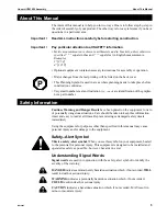
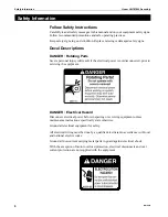
Страница 5: ...not a part number Safety Information Caution Warning and Danger Decals have been placed on the equipment to warn of potentially dangerous situations Care should be taken to keep this information intac...

Страница 6: ...the electrical power is not disconnected prior to servicing the equipment DANGER Electrical Hazard Disconnect electrical power before inspecting or servicing equipment unless maintenance instructions...

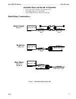
Страница 7: ...Weight Capacity of the Lift is 800 lbs Cable Pulley Combinations Same Speed Ratio 1 1 Linear LiftTM 800 12 Minute 800 lb max Load 12 Minute 800 lb max Load Speed Up Ratio 1 2 Linear LiftTM 800 12 Minu...

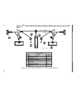
Страница 8: ...LiftTM 800 Item Description Part Number 1 Inlet Spring Close Doors 41143 2 Tie Down 3 Double Pulley Assembly 43272 4 Linear LiftTM 800 Open Doors 41920 18 5 Curtain Cable 6 Hand Winch Winch Mounting A...

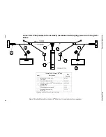
Страница 9: ...ription Part Number 1 Inlet Spring Close Doors 41143 2 Tie Down 3 Double Pulley Assembly 44520 4 Chain Drive Linear LiftTM 800 Open Doors 44458 18 5 Curtain Cable 6 Hand Winch Winch Mounting Assembly...

Страница 10: ...l wall view Grease Recommendation The LINEAR LIFTTM is fully greased at the factory However for maximum life Chore Time strongly recommends greasing the Linear LiftTM 800 at each grease fitting monthl...

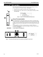
Страница 11: ...n the set screw on the Set Collar see Item 2 below Slide the Set Collar s on the Switch Rod allow for the maximum inlet opening travel see Item 4 below Figure 10 shows the maximum travel settings at a...

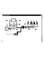
Страница 12: ...Wiring Diagram Wiring Diagram Linear LiftTM 800 Assembly 12 MV1654F...

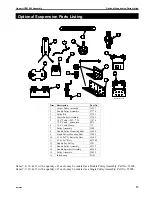
Страница 13: ...Pulley Mounting Brkt 35404 9 Single Pulley Mounting Brkt 35405 10 3 16 18x7 U Bolt with Nuts 35602 11 5 16 18x7 Bolt 4412 20 12 Double Eye Pulley 2501 13 Double Pulley Assembly 43272 14 Double Sprocke...

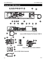
Страница 14: ...Linear LiftTM 800 Parts List Linear LiftTM 800 Parts List Linear LiftTM 800 Assembly 14 MV1654F...

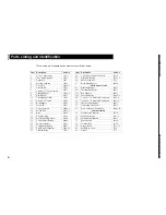
Страница 15: ...Support 44459 9 End Bracket 41913 14 Cover Assembly 56086 2 10 Threaded Shaft Pilot 35569 29 1 4 20 x 1 1 2 Socket HD Cap Screw 5083 8 11 Linear LiftTM Cable 41342 30 1 4 20 x 2 1 4 Socket HD Cap Scre...

Страница 16: ...different from the authoritative CTB published English version of the manual For current product installation and operation information please contact the customer service and or technical service dep...

Отзывы: