


19
Chloride Active
UK
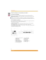
4.2.1.2 Operation
The following chart describes functions and operations of these buttons and LEDs
(*) These LEDs show battery capacity level or output load level (depending on button 5) and normally they should be read
as a group. However, in case of certain events (SWF, Battery Fault, UPS Fault or UPS Overload), they pass to indicate it by
ashing and should be read individually.
Button/LED
Function
Operation/De nition
Button 14
Inverter ON/OFF Button
Press one second to switch on/off the inverter
Button 7
Site Wiring Fault E/D Button
Press seven seconds to enable/disable Site
Wiring Fault detection
Button 6
Mute Buzzer (Alarm Reset)
Press one second to mute the buzzer
LED test
Press for LED test (all LEDs ashing)
Force the unit to bypass or
comeback
Press buttons 6 and 5 for four seconds to force
the unit to bypass or to return from bypass
Reset LCM Alarm (alarm which
indicates end of estimated
battery life)
Press buttons 6 and 5 for three seconds to
reset this alarm (if the alarm is active, it is
necessary to push these buttons 4 more
seconds to switch the unit to bypass, as per
above functionality)
Button 5
Show Output Load level
Press to show output load level on LEDs 1, 2
3 and 4 (by default they show battery capacity
level)
Cold Start Enable/Disable
Press ve seconds to enable/disable cold start
functionality
LED 1 (*)
Site Wiring Fault Detection LED
Indicates if Site Wiring Fault has been detected
LED 2 (*)
Battery Fault LED
Indicates if a battery fault has been detected
LED 3 (*)
UPS Fault LED
Indicates if a UPS fault has been detected
LED 4 (*)
UPS Overload LED
Indicates if an output overload has been
detected
LEDs 1, 2, 3
& 4 (*)
Battery Capacity Level / Output
Load Level
Indicates battery capacity level (by default), or
output load level if button 5 is pressed
LED 8
Site Wiring Fault E/D LED
Indicates if Site Wiring Fault detection is enabled
or disabled (enabled: ON; disabled: OFF)
LED 9
Outlet 1 ON/OFF LED
Indicates if group 1 of the output controllable
sockets is supplying power or not (supplying
power: ON; not supplying power: OFF; status
change in progress: ashing)
LED 10
Outlet 2 ON/OFF LED
Indicates if group 2 of the output controllable
sockets is supplying power or not (supplying
power: ON; not supplying power: OFF; status
change in progress: ashing)
LED 11
Bypass Mode LED
Indicates if the unit is on bypass mode ( ashing)
LED 12
Line Mode LED
Indicates if the unit is on line mode (ON)
LED 13
Battery Mode LED
Indicates if the unit is on battery mode (ON)
LED 15
Inverter ON LED
Indicates if the inverter is ON or OFF
Содержание Power Protection Active 1000
Страница 1: ...UK ...
Страница 2: ...1 Chloride Active UK ...
Страница 3: ...1 Chloride Active ENGLISH DEUTSCH ESPAÑOL FRANÇAIS ITALIANO PORTUGUÊS UK DE E FR I P ...
Страница 38: ...36 UK Chloride Active 945044 066 Tower models Rack Tower models ...